عضویت
عضویت  ورود اعضا
 راهنمای خرید


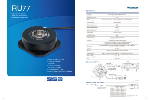
BS78 Series0 pages
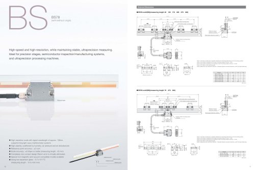
BSBS78
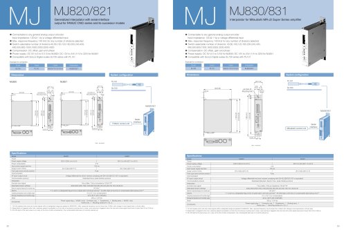
(with/without origin)
10 11
Actual size
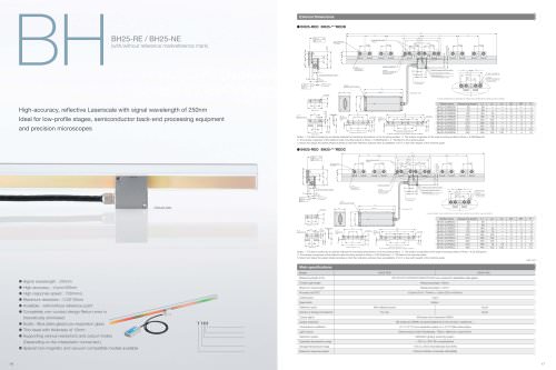
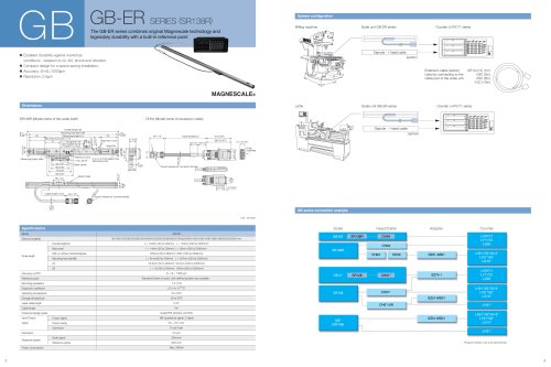
• High-resolution scale with signal wavelength of approx. 138nm,
outperforming light wave interferometer systems
• High stability, unaffected by humidity, air pressure and air disturbances
• Reference point accuracy : ±0.1ìm
• Scale accuracy : ±0.04ìm or better (measuring length : 40 mm)
• Completely non-contact design Return error is virtually eliminated.
• Special non-magnetic and vacuum-compatible models available
• Using low expansion glass : -0.7 x 10⁻⁶/ °C
(measuring length : 10 to 420 mm)
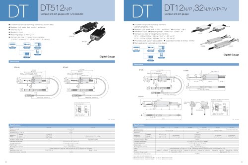
High-speed and high-resolution, while maintaining stable, ultraprecision measuring.
Ideal for precision stages, semiconductor inspection/manufacturing systems,
and ultraprecision processing machines.
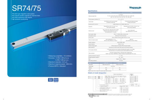
Type example F BS78-220R
R: with reference point;
RS: high accuracy with reference point
N: without reference point;
NS: high accuracy without reference point
Effective length
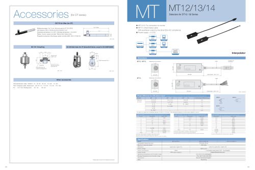
External Dimensions
L1 1
50 3*
60
L3 1 L21 L2 1 L3 1
25
38
Spacer t=2
10
25±0.2* 25±0.2* 25±0.2* 25±0.2* 25±0.2*
2-M4 reference plate mounting screw
N-M4 scale clamp mounting screw
Scale movement
Reference point
detection direction
38 0.2*
3 46 0.3
29.5
43.5
32.7 0.3
Detector head mounting screw
2-M3x30
45.9 15
40.5
ø7
Cable length
3000
Reference signal
detection position
Scale signal detection position
0.01 M
0.01
A *
4.6
6
13.1
9.8 0.2*
0.*03 A
30.5
5 14
13.3
6.8
Reference plate t=2
Reference
hole
25
50
42
60
9
14
ø4+0.05 3-ø5
0
2-ø5
Scale clamp
25
5
12
38
ø4+0.05
0
4+0.05
0
Unit: mm
Model
BS78-40R (RS)
BS78-120R (RS)
BS78-170R (RS)
BS78-220R (RS)
BS78-370R (RS)
BS78-420R (RS)
L1
66
146
196
246
396
446
L2
—
50
75
100
75
100
L3
—
—
—
—
75
100
N
2
6
6
6
10
10
Unit: mm
Model
BS78-70R (RS)
BS78-270R (RS)
BS78-320R (RS)
L1
96
296
346
L2
—
120
120
N
4
8
8
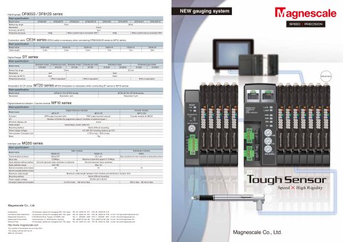
Note 1:The items marked by an asterisk indicate the machining dimensions on the mounting surface.
Note 2:The surface roughness of the scale mounting surface is Rmax = 6.3S.
Note 3:The surface roughness of the detector head mounting surface is Rmax = 12.5S.
Note 4:"M" refers to the machine guide.
Note 5:Reference point detection direction : Standard (Scale movement direction with the head stationary)
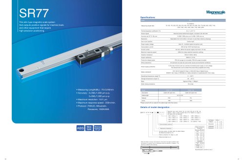
L1 1
Spacer t=2
10
25
38
Detector head mounting screw
2-M3x30
L21 L2 1
Scale movement
Reference point
detection direction
40 0.2*
88 0.3*
25 0.2* 25 0.2* 25 0.2* 25 0.2*
98
N-M4 scale clamp mounting screw
2-M4 reference plate mounting screw
39.2 0.2*
14
5
23
38 0.2*
46 0.3
43.5
29.5
3
32.7 0.3
45.9 15
40.5
ø7
Cable length
3000
6.8
13.3
Reference signal
detection position
Scale signal detection position
0.01 M
0.01
A *
0.*03 A
9.8 0.2*
13.1
30.5
6
4.6
Scale clamp
38
25
5
12
1.4
16
21
0.4
13.8
ø4+0.05
0
4+0.05
0
Reference
hole
9
14
42
60
25 15 25
88
98
5-ø5
2-ø5
ø4+0.05
0
Reference plate t=2
BS78-xxxN(NS)(measuring lengthF40^120^170^220^370^420)
BS78-xxxN(NS)(measuring lengthF70^270^320)
0.4 1.4