عضویت
عضویت  ورود اعضا
 راهنمای خرید


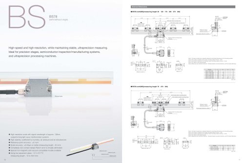
BSBS78 (with/without reference mark)0 pages

BS78-xxxN(NS)(measuring length 40
120
170
220
370
420)
L1 1
L3 1
L2 1
(with/without reference mark)
L3 1
13.1
9.8 0.2*
N-M4 scale clamp mounting screw
60
2-M4 reference plate mounting screw
50 3*
Scale movement
25 0.2* Reference point
25 0.2*
detection direction
*
0.01 M
0.01
A
L2 1
25 0.2*
25 0.2*
25 0.2*
6
14
BS78
5
4.6
Reference signal
detection position
43.5
32.7 0.3
BS
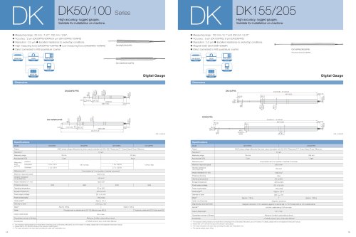
External Dimensions
Scale signal detection position
30.5
Detector head mounting screw
2-M3x30
29.5
38 0.2*
46 0.3
3
45.9
ø7
Cable length
3000
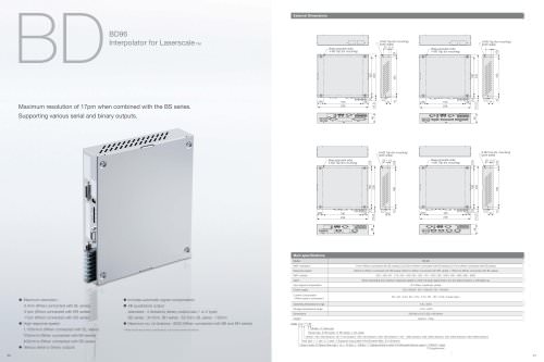
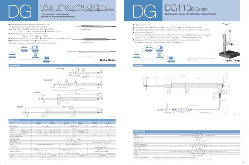
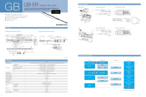
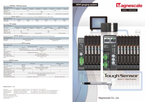
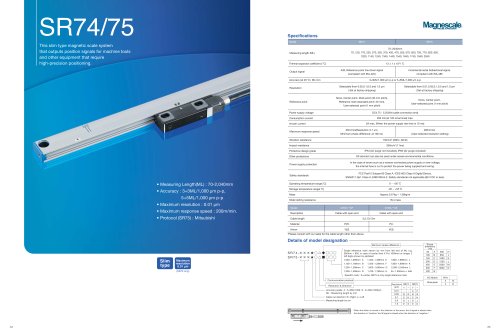
High-speed and high-resolution, while maintaining stable, ultraprecision measuring.
*
0.03 A
15
6.8
40.5
Ideal for precision stages, semiconductor inspection/manufacturing systems,
ø4 +0.05
0
3-ø5
9
0.4
1.4
10
ø4 +0.05
0
Reference
hole
Note 1:The items marked by an asterisk indicate the machining dimensions on the mounting surface.
Note 2:The surface roughness of the scale mounting surface is Rmax = 6.3S.
Note 3:The surface roughness of the detector head mounting surface is Rmax = 12.5S.
Note 4:"M" refers to the machine guide.
Note 5:Reference point detection direction : Standard (Scale movement direction with the head stationary)
2-ø5
25
5
4 +0.05
0
50
25
14
13.3
and ultraprecision processing machines.
42
25
38
12
60
38
Reference plate t=2
Model
BS78-40R (RS)
BS78-120R (RS)
BS78-170R (RS)
BS78-220R (RS)
BS78-370R (RS)
BS78-420R (RS)
Spacer t=2
Scale clamp
L1
66
146
196
246
396
446
L2
—
50
75
100
75
100
L3
—
—
—
—
75
100
N
2
6
6
6
10
10
Unit: mm
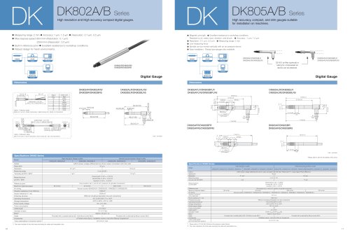
BS78-xxxN(NS)(measuring length 70
270
320)
L1 1
*
0.01 M
0.01
A
L2 1
L2 1
98
88 0.3*
40 0.2*
Actual size
(measuring length : 10 to 420 mm)
10
Scale signal detection position
40.5
42
60
Reference plate t=2
reference point
5
2-ø5
16
0.4
12
38
Scale clamp
1.4
10
25
13.8
5-ø5
21
ø4 +0.05
0
25
14
15
9
25
4+0.05
0
88
ø4 +0.05
0
Reference
hole
*
0.03 A
Note 1:The items marked by an asterisk indicate the machining dimensions on the mounting surface.
Note 2:The surface roughness of the scale mounting surface is Rmax = 6.3S.
Note 3:The surface roughness of the detector head mounting surface is Rmax = 12.5S.
Note 4:"M" refers to the machine guide.
Note 5:Reference point detection direction : Standard (Scale movement direction with the head stationary)
98
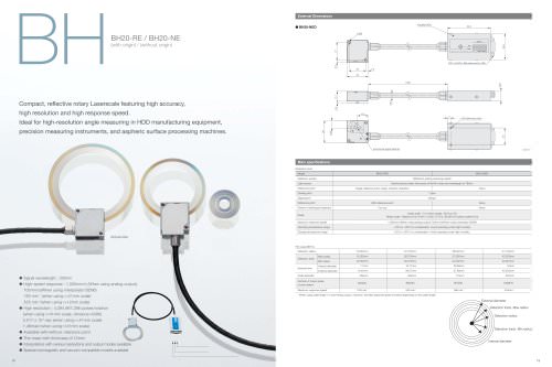
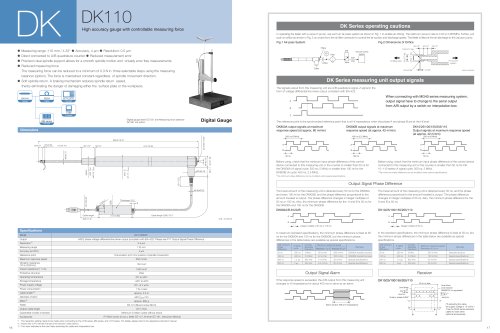
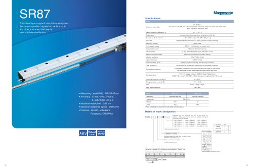
outperforming light wave interferometer systems
High stability, unaffected by humidity, air pressure and air disturbances
Reference signal
detection position
15
45.9
6.8
• High-resolution scale with signal wavelength of approx. 138nm,
-6
6
4.6
Detector head mounting screw
2-M3x30
29.5
38 0.2*
46 0.3
ø7
Cable length
3000
•
• Reference point accuracy : ±0.1μm
• Scale accuracy : ±0.04μm or better (measuring length : 40 mm)
• Non-contact design eliminates return error.
• Special non-magnetic and vacuum-compatible models available
• Using low expansion glass : -0.7 x 10 / ˚C
25 0.2*
30.5
3
13.3
2-M4 reference plate mounting screw
25 0.2*
14
23
39.2 0.2* 5
25 0.2*
N-M4 scale clamp mounting screw
32.7 0.3
43.5
25 0.2*
Scale movement
Reference point
detection direction
13.1
9.8 0.2*
25
38
Spacer t=2
Model
BS78-70R (RS)
BS78-270R (RS)
BS78-320R (RS)
L1
96
296
346
L2
—
120
120
N
4
8
8
Unit: mm
reference point
reference point
reference point
11