عضویت
عضویت  ورود اعضا
 راهنمای خرید


MG series0 pages
40 41
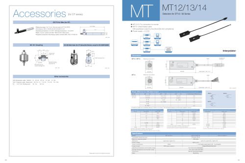
Interface module
Model name
Power consumption
I/O
Output setting
MG30-B1
source input (+com)
sink type (–com)
MG30-B2
sink input (–com)
source type (+com)
1w
Photo coupler insulation, external power: DC5 – 24V
Photo coupler insulation, external power: DC5 – 24V
DRQ / channel address / measuring mode shifting / comparator shifting / reset / start / posing / reference point loaded
BCD data (6 digits) / READY / code / GO/NO GO output / alarm / reference point loaded
timer (1~128ms) / OUT / OR / polarity (set with internal DIP switch)
Input format
Output format
Input signal
Output signal
All models Operating temperature
Storage temperature
0~+50°C (No condensation)
–10~+60°C (20~90%RH)
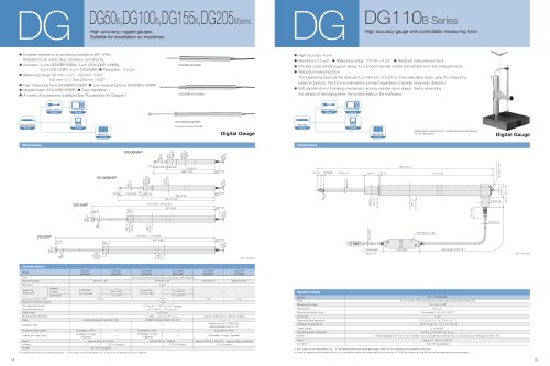
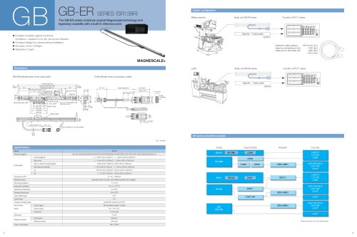
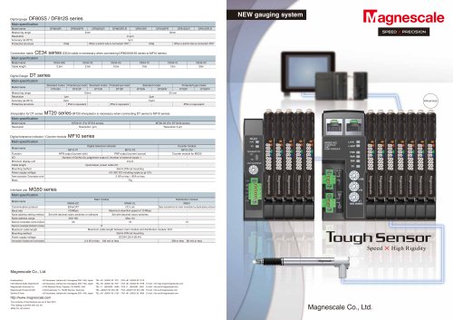
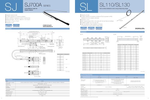
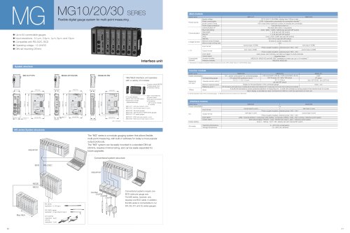
System structure
• Up to 64 connectable gauges
• Input resolutions : 0.1ìm, 0.5ìm, 1ìm, 5ìm, and 10ìm.
• Compatible with RS-232C, BCD
• Operating voltage : 12-24VDC
• DIN rail mounting (35mm)
MG MG10/20/30 SERIES
*1: Total power of modules connected to MG10 should not be over 54W (12VDC Input) or 108 W (24VDC Input).
Model name
Power source
Communication
Linkage function
I / O
Connectable
modules
Supply voltage
Power consumption
Inrush current (10ms)
Power supply protection
Communication I/F
Baud rate setting
Data length
Stop bit
Parity
Delimiter
Maximum number of linkages
Maximum length of linking cable
DC12-24V(11-26.4V)Min. startup time: 100ms or less
2.0W + total power consumption for connected modules*1
10A or less (when maximum number of modules are connected)
Fuse (5A fuse is built in.)
RS-232C (EIA-232C or equivalent)
2400 / 9600 / 19200 / 38400 bps (set with DIP switch)
7 / 8 bit (set with DIP switch)
1 / 2 bit (set with DIP switch)
none / ODD / EVEN (set with DIP switch)
CR / CR+LF (set with DIP switch)
16 (total of counter modules: 64)
10m
Photo coupler insulation, external power: DC5 – 24V
Photo coupler insulation, external power: DC5 – 24V
reset, pause, start, latching, and data out trigger to whole channels
integrated alarm
MG20-DK, MG20-DG and MG-20DT (available for mixed use, up to 16 modules) *1
MG30-B1,MG30-B2
Input format
source input (+COM)
sink type (–COM)
sink input (–COM)
source type (+COM)
MG10-P1 MG10-P2
Output format
Main module
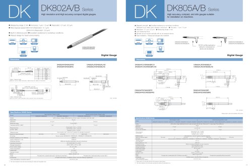
DK series
resolution : 0.1/0.5ìm
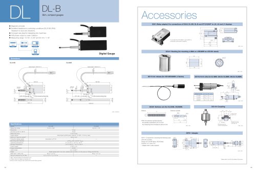
DG- B/DL series
resolution : 0.5ìm/5ìm/10ìm
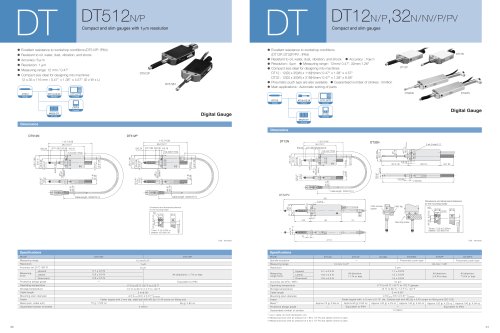
DT12,DT32
resolution : 5ìm
DT512
resolution : 1ìm
*2: Set the resolution value of the connected gauge. *3: MG20-DG work only connect to DL**BR series
Model name
Power consumption
Corresponding gauge
Maximum response speed
Reference point *3
MG20-DK MG20-DG MG20-DT
1W + power consumption for connected gauge
DK series (A/B quadrature input)
10 / 5 / 1 / 0.5 / 0.1ìm
1.4W (connected to DG-B) / 0.5W (connected to DL-B)
DG**B series, DL**B/DL**BR series
10 / 5 / 0.5ìm
set with DIP switch
S-ALM LED activates by excess speed/acceleration of measuring unit. C-ALM LED activates by excess speed of the internal circuit of counter.
Alarm display is cancelled by reset command from MG10 or with the reset button of main unit.
0.8W
DT series
5ìm (DT12/32) 1ìm (DT512)
100m / min
–
Measuring
unit input
Others Alarm
Subject to the specification of the connected gauge
Allowable resolution setting *2
REF-LED (reference point loaded) shows on the display after the reference point is detected. Set “0” or preset value on the counter when the reference point is detected.
Counter module
Interface unit
MG series System structures
“MG”Multi Interface unit operates
with a variety of modules.
Counter module (MG20)
• Digital gauge input
• Resolution setting
Main module (MG10)
• Power supply
• RS-232C Connection
• Connection
with Counter module,
I/F module
I/F module (MG30)
• BCD / GO / NO GO output
• Expansion module
(Sequential lineup)
MG10-P1 : sink type output (–com)
MG10-P2 : source type output (+com)
MG30-B1 : BCD sink type output (–com)
MG30-B2 : BCD source type output (+com)
MG20-DK : DK series gauges
MG20-DG : DG**B and DL**B/BR series gauges
MG20-DT : DT series gauges
sequencer
BCD RS-232C
MG30
MG10
Max16ch
The "MG" series is a modular gauging system that allows flexible,
multi-point measuring, with built-in software for today's most popular
output protocols.
The "MG" system can be easily mounted to a standard DIN rail
(35mm), requires minimal wiring, and can be easily expanded for
future upgrades.
Conventional systems require one
BCD cable per gauge axis.
The MG series, however, only
requires one BCD cable. In addition,
the MG series is connectable to our
DK, DG, DT, and DL series gauges.
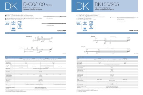
Unit : mm/inch
sequencer
counter
counter
counter
counter
Conventional system structure
MG10-P1/P2
35.65/1.40 4.35/0.17
33.1/1.3
64.5/2.54
64/2.52
108.5/4.27
105/4.13
99/3.9
RS-232C
LINK-IN
LINK-OUT
FG
DC-IN
I/O
232C-SET
Unit No.
MG30-B1/B2
24.5/0.96
20.5/0.81
64.5/2.54
64/2.52
105.5/4.15
99/3.9
BCD I/O
MG20-DT/DG/DK
4.35/0.17
23/0.91
20.5/0.81
64.5/2.54
64/2.52
108.5/4.27
105/4.13
99/3.9
SIG
DIR
RES
ADDRESS
RESET
MG20-DK
Input signal
Output signal
Counter modules
Interface modules
Flexible digital gauge system for multi-point measuring .