عضویت
عضویت  ورود اعضا
 راهنمای خرید


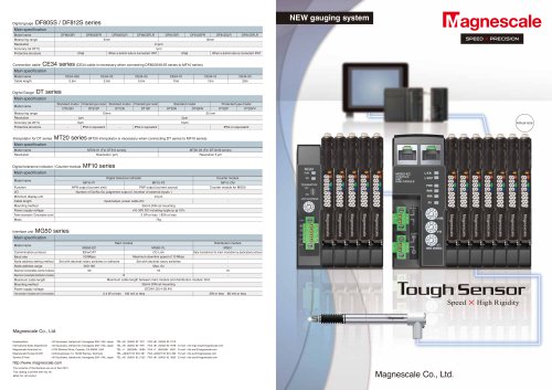
MT series0 pages
A, B, ALARM
A, B, ALARM
_ _ _
MT14
A, B
A, B
_ _
MT13
A, B, ALARM
MT12
32 33
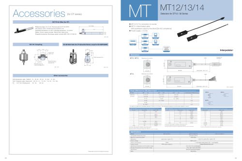
Interpolator
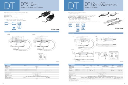
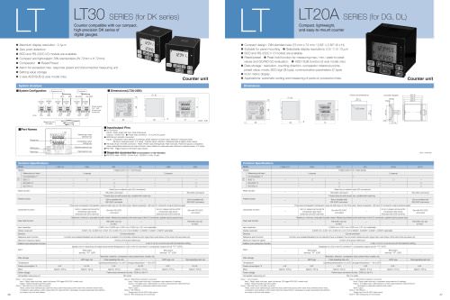
Detectors for DT12 / 32 Series MT MT12/13/14
Dimensions
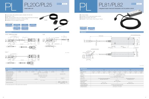
• MT12/13: For connection to counter
• MT14: Unterminated cable
A/B-quadrature output by line driver [EIA-422 compliance]
• Power supply + 5 V DC
Unit : mm/inch
MT12 / MT13
MT14
Measuring unit connector
25/0.98"
32/1.26"
98/3.86" Cable length : 300/11.81"
Cable Counter unit
connector
Measuring unit connector
25/0.98"
32/1.26"
98/3.86" Cable length : 300/11.81"
Cable
Model MT12-05/10
5ìm(-05), 10ìm(-10)
0.9 W
NPN open collector
MT13-01/05/10 MT14-01/05/10
Compatible measuring units
Maximum response speed
Resolution
Power voltage
Power consumption
Output format
Operating temperature and humidity range
Storage temperature and humidity range
Dimensions
Mass
DT12/32, DT512
100 m/min
DC5 V ±4 %
0 to +50 °C (no condensation)
-10 to +60 °C (20 to 90 %RH)
See the Dimensional Diagram.
About 90 g
Specifications
1ìm(-01), 5ìm(-05), 10ìm(-10)
1.2 W (when output load of 120Ù is connected)
Voltage differential line driver
The control
unit of
respective
company
DT12/32, DT512 LT30
MT12 LT20A
MT13
MT14
Phase difference for A/B phase output Changes as follows according to the traveling velocity of the measuring unit.
Model MT -01
0 to 2.5
to 6.25
to 12
to 24
to 60
to (100) *
MT -05 MT -10 Output phase difference (ìs)
Velocity
(m/min)
0 to 12.5
to 31.25
to 60
to (100)*
–
–
0 to 25
to 62.5
to (100)*
–
–
–
20
8
5
2.5
1
0.5
* An alarm is output at a traveling velocity of 100 to 115 m/min. The sampling frequency of the output signal is 120 ìs.
Cable color MT12
Pin no. Description Cable color
1
2
3
4
5
6
7
8
9
10
Case
+5 V
–
0 V
A
B
–
–
ALARM
0 V
0 V
FG
Red
–
Black
Yellow
Blue
–
–
Gray
Purple
Orange
Shield
Connector used: Hosiden TCP8938 or equivalent product
0V and the shield (FG) are connected with a capacitor.
Nothing should be connected to cables with colors not found in this table.
Output signal : A/B phase, Alarm Output format : NPN open collector output
(maximum rated voltage: 31 V, maximum rated current: 50 mA) Cable color MT14
Description Cable color
+5 V
0 V
0 V
0 V
A
A
B
B
ALARM
ALARM
FG
Red
White
Brown
Black
Yellow
Blue
Gray
Orange
Purple
Green
Shield
0V and the shield (FG) are connected with a capacitor.
Output signal : A/B phase, Alarm (The output does not become high impedance during an alarm.)
Output format : Voltage differential line driver output (compliant with EIA-422)
_
_
_
Cable color MT13
Pin no. Description Cable color
1
2
3
4
5
6
7
8
Case
+4.5 V
0 V
A
A
B
B
–
–
FG
Purple
Black
Blue
Yellow
Orange
Gray
–
–
Shield
Connector used: Hosiden TCP8938 or equivalent product
0V and the shield (FG) are connected with a capacitor.
Nothing should be connected to cables with colors not found in this table.
Output signal : A/B phase (The output becomes high impedance during an alarm.)
Output format : Voltage differential line driver output (compliant with EIA-422)
_
_
8.5 16.5 5
15
ø18
Fixing screw
(3-M 3 x 5)
Nut (M 5) Spindle mounting
screw (M 2.5)
Mounting screw for
machine carriage (M 5)
Unit : mm
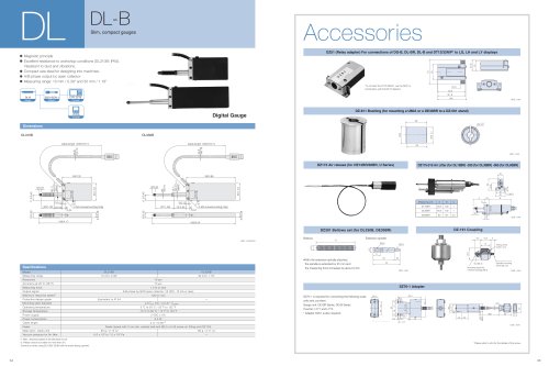
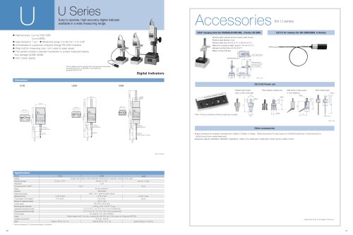
DZ-100 Roller feeler (for DT Series,DG-B Series: except for DG155BP/205BP)
Roller thickness:4mm
ø12
ø10
7
22
M2.5
Unit : mm
DZ-191 Coupling
DZ176 Air lifter (for DT)
102.7 (Max)
77.7
ø10
unit : mm
•Measuring range: 0 to 12 mm •Can be used for DT12/512P/N
•Air pressure: 250 to 700 kPa (25,48 to 69,58 N/ cm2)
•Operating temperature: 0 to 50°C •Storage temperature: -10 to 60°C
•Mass: 41g (incl. speed controller) •Service life:5 million times
•Supplied accessories: Mounting jig, speed controller (SMC: AS1211F-M5-04)
Other accessories
•CE-08 Extension cable F CE08-01i1mjA03i3mjA05i5mjA10i10mjA15i15mj
•CK-T Extension cableiAhead-proofjF CK-T12i1mjAT13i3mjAT14i5mjAT15i10mj
•C‚j-‚s101/T105iWinding-proofjF ‚s101i3mjA ‚s105i5mjS
Accessories (for DT series)
*Please refer to p54 for the details of the screw.