عضویت
عضویت  ورود اعضا
 راهنمای خرید


MJ100/1100 pages
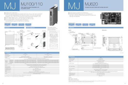
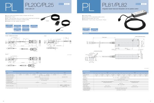
Compact one-axis module with analog input port MJ MJ620
• Divides analog input signal into 32 to 800 divisions.
• Produces AB quadrature signal output from the differential line
driver when combined with SL700 series scale and PL101 series head
cable (both sold separately).
Dimensions
Unit : mm/inch
SL700 PL101 MJ620
Scale Head Interpolator
Example for connection
CE08 CK-T12/13/14/15/16
Cable
13.2/
0.519
Model MJ620
5 V (4.5 to 6 V)
2.2 W (with PL101)
Line driver (EIA-422 compliance)
AB quadrature, Z, Alarm
6.4 m/s (with phase difference of 100 ns and resolution of 1 ìm)
16 m/s (with phase difference of 100 ns and resolution of 2 ìm)
36.8 m/s(with phase difference of 100 ns and resolution of 5 ìm)
56 m/s (with phase difference of 100 ns and resolution of 10 ìm)
100 ns
0.5s or less after powering up
0 °C to +45 °C / 32 °F to 114 °F
-20 °C to +60 °C / -4 °F to 140 °F
60 g/ 2.12 oz
Power supply voltage
Power consumption
Output interface
Output
Number of division
Min. phase difference
System starting up time
Operating temperature
Storage temperature
Mass
Specifications
Options
Max. response speed
Input level
Alarm
800,400,160,80,40,32
(Correspond to resolution 1,2,5,10,20,25 ìm)
And 1/2 of this (But concurrent reference point not satisfied)
SIN. COS signal 0.6 Vp-p to 1.2 Vp-p at 120 Ù load
Reference signal 0.2 V to 1.5 V at 120 Ù load
Speed alarm (min. phase difference time or max. response frequency), Level alarm (0.6 Vp-p or less), Min. alarm time about 400 ms
NOTE: Alarm may not work due to abnomal offset occurred by breakage etc.
*The MJ620 Interpolator meets the "applied standards" stated in the specifications table when fitted with the optional MZ5 metal case (see below).
Make sure that the MJ620 is used with the MZ5 or like case with the same specifications as MZ5.
MZ2: Output connector
MZ5: Metal case for MJ620
59/2.32
55/2.16
48/1.88
2/0.07
3.5/0.13
4-ø3.5/ø0.13 Mounting holes
2/0.07
8/0.31
(4/0.15)
90/3.54
8/0.31
17/0.66
1.6/0.06
4/0.15 21/0.82 65/2.55
93.5/3.68
(1.5/0.05)
(5.4/0.21)
Area appropriated for board
and mount parts
37/1.45
Sensor input connector
HOSHIDEN:TCS7587-01-401
Output connector
HONDA:PCR-E20LMD
MJ620
9.6/0.37
33.4/1.31
15/0.59
13.5/0.53
11/0.43
(3.5/0.13)
(3.5/0.13)
2/0.07
7.5/0.29 7.5/0.29
MZ5(Option)
23/0.90
ø4.5/ø0.17
120/4.72
110/4.33
4.5/0.17
62.5/2.46
1/0.03
100/3.93
(104/4.09)
4.5/0.17
ø13/ø0.51 26/1.02 22.5/0.88
11.1/0.43
5/0.19
11/0.43
MJ100
MJ110
PL25
PL60
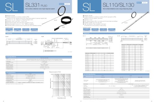
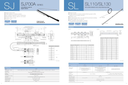
SL110/130
Interpolator
Head cable unit
Scale unit
SL331
High response speed interpolator unit
for position control MJ MJ100/110
• Capable of 40 to 1000 divisions
• Produces AB quadrature signals with a resolution from 2 ìm to 125 ìm, when used in combination
with the optionally available Digiruler® PL25 head unit and the SL110/130 scale unit (scale signal
wavelength: 5 mm), or with the PL60 and the SL331 scale unit (scale signal wavelength: 2 mm).
• MJ100: Supply voltage 5 V input, Line driver (EIA-422 compliance) output
• MJ110: Supply voltage 12 to 30 V input, Open collector (lOL=50 mA) output
• MJ100 also generates U/ V/ W phase output with a period of
reproduced Digiruler® signal (5 mm with PL25; 2 mm with PL60)
Unit : mm/inch
Dimensions System Configuration
SL331 PL60 MJ100/110
Scale Head Interpolator
Example for connection
CE08 CK-T12/13/14/15/16
Cable
Model MJ100 MJ110
Within 0.5 seconds after the power comes on line
138 x 93 x 26 (mm) / 5.43" x 3.66" x 1.02" including protrusions
PL25 or PL60
0 °C to +45 °C / 32 °F to 113 °F
-20 °C to +60 °C / -4 °F to 140 °F
350g/ 0.77Ibs
Manual, output connector, connector cap, mounting screws
Power supply
Power consumption
Output interface
Outputs
Specifications
*1: These valuse for a minimum phase difference of 1 ìs may vary depending on the output cable length.
*2: The alarm function may not operate when an abnormal offset is generated due to a broken wire, etc.
*Contact us directly if you have special requirements for the specifications.
1000 divisions
500 divisions
200 divisions
120 divisions
Speed alarm (minimum phase difference time or maximum response frequency);
Level alarm (0.4 Vp-p or less); Minimum alarm time: approximately 400 ms
1000,960,800,512,500,480,400,256,240,200,128,120,100,80,64,40
and 1/2 of each of these (which does not satisfy the synchronized reference point specifications.)
5 V (4.5 V to 6 V)
4 W
Line driver (EIA-422 compliance)
AB quadrature, Z phase, U/V/W phases, alarms
12 V to 30 V (11 V to 31 V)
3 W
Open collector (IOL = 50 mA max.)
AB quadrature, Z phase, alarms
6 KHz (1800 m/min when connected to PL25; 720 m/min when connected to PL60)
15 KHz (4500 m/min when connected to PL25; 1800 m/min when connected to PL60)
42 KHz (12600 m/min when connected to PL25; 5000 m/min when connected to PL60)
70 KHz (21000 m/min when connected to PL25; 8400 m/min when connected to PL60)
100 ns
600 KHz (180 m/min when connected to PL25; 72 m/min when connected to PL60) *1
1.5 KHz (450 m/min when connected to PL25; 180 m/min when connected to PL60) *1
4.0 KHz (1200 m/min when connected to PL25; 480 m/min when connected to PL60) *1
7.4 KHz (2220 m/min when connected to PL25; 888 m/min when connected to PL60)*1
1ìs
SET-P16-1 (for external reference point) Scale extension cable, external reference point extension cable
Output connector with cable
Maximum
response
frequency
Alarms *2
Options
System startup time
External dimensions
Compatible head unit
Operating temperature
Storage temperature
Mass
Supplied accessories
Number of divisions
Minimum phase difference
ALM
LEVEL
SPEED
MJ100
OFF OFF
ON OFF
OFF ON
ON ON
ABS
1
1 2 3 4 5 6 7 8 9 10
2 3 4 5 6 7 8 9
10
MODE
ON OFF
93/3.66
1/0.03
110/4.33
(115/4.53)
26/1.02
(13/0.51) 13/0.51
ø4.5/ø0.17 3/0.12
138/5.43
124/4.88
4.5/0.18
Phase Relation between
MJ100 Input Signals, U/V/W
Phases and AB Phases
The following diagrams show
the MJ100’s scale input signal phases with
respect to the output signal phases
When MODE switch 4 and 5 are off
COS
SIN
Z
U
V
W
Z
A
B
U
50 51