عضویت
عضویت  ورود اعضا
 راهنمای خرید


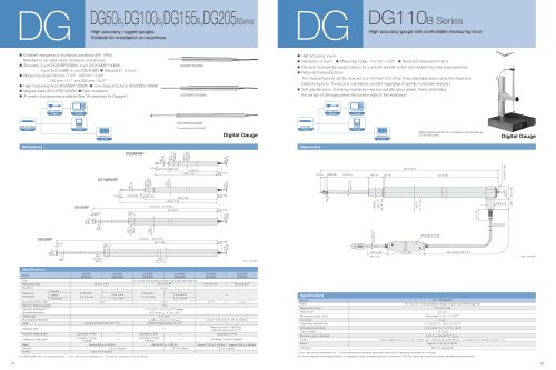
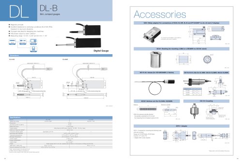
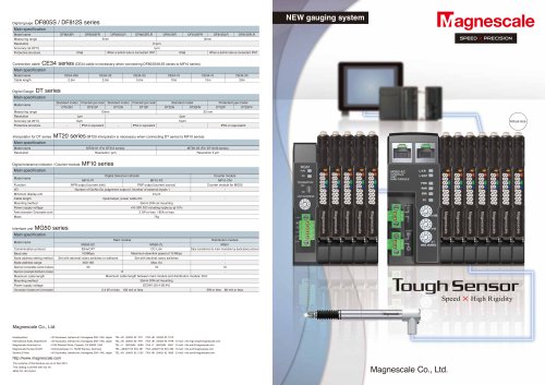
Magnescale LH700 pages
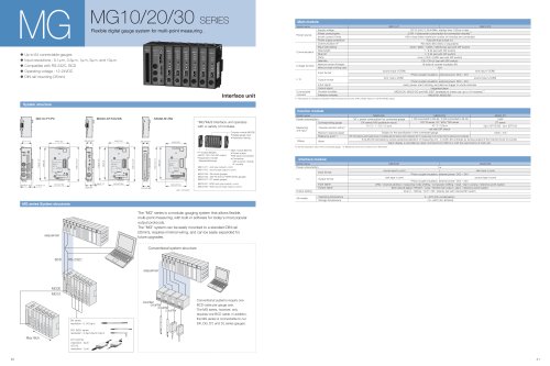
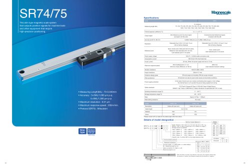
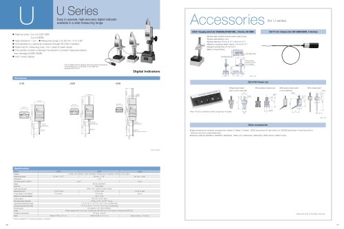
LH 70/71 SERIES
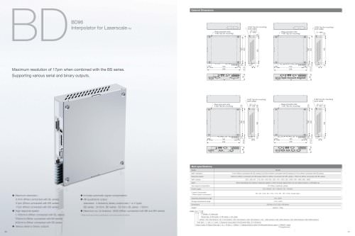
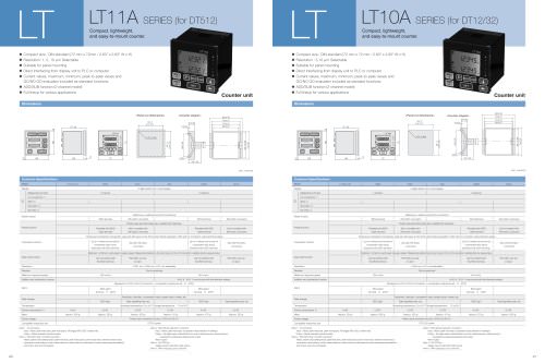
nnnnHigh performance counter for Mille and Lathe applications.
nnnnCounter for Milling machine (LH70/71) and Lathe (LH70-3/LH71-3)
nnnnDisplay Resolution Switching
nnnnMachine error compensation
nnnnData Storage. • Reset/Preset
nnnnReference Point Detection
nnnnProgram function • Mufti datum point • Scaling
nnnnMilling function (Bolt hole circle/Easy Radius cutting/Line hole)
nnnnLathe function (Tool coordinating / Adding function)
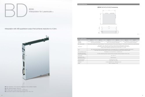
nnnnSpecifications
nnnnCommon Specifications
nnnnModel | LH70/71-1 | LH70/71-2 | LH70/71-3 |
Display | 7 digits and minus display, Color amber | ||
Connectable measuring unit | GB-ER, SJ300 series, SJ700A, PL2CC series (Direct) DG-B (Necessary to use the conversion adaptor which Is sold separately.) | ||
Measuring unit input resolution | Standard: 0.1 um, 0.5 urn, 1 um, S urn, 10 urn, 1 s, 10 s, 1 min, 10 min Expanded: 100 urn, 50 um, 25 jim, 20 um, 2 um, 0.05 um and 1 degree can be added. | ||
Display resolution | Measuring unit input resolution or higher and diameter display (except for angle display) | ||
Input signal | A/B quadrature signal, Z signal (Conforms to EIA-422.) | ||
Mlnrnum hput phase difference | 100 ns | ||
Quantization error | ±1 count | ||
Alarm display | Measuring unit disconnected, Excess speed, Maximum display amount exceeded, Power failure, Error in stored data | ||
Reset | Resettable by key switch | ||
Preset | It is possible to store/call 3 kinds of numbers. | ||
Reference point detection | The reference point of the measuring unit can be detected, and the datum point can be relocated (during connection of measuring unit with a reference point) | ||
Datastorage | The value displayed before the power was turned off and setting values are stored | ||
Linear error compensation | A fixed compensation is applied to the measuring unit's count value. Compensation amount Standard: ±600 um/m (Expanded: ±1000 um/m) | ||
Segmented error compensation | The movement range of the measuring unit with a reference point can be divided Into amaxlmum of 32 sections, and error compensation Is performed for each of these sections, Compensation amount: ±600 um (at each sectlon)(LH71 only) | ||
Scaling | Scaling factor: 0.100000 to S.99999S(LH71 only) | ||
Program | Machining coordinates can be programmed (number of program steps: 850 max.) 1. Manual programming by key switch 2. Automatic programming by playback 3. Mirror image during program execution 4. A canned cycle (bolt hole, line hole, simple R cutting) can be inserted in the program. (LH71 only) | ||
Angle display | Can be displayed as an angle value when the Diginjler is pasted to the arc surface, and the diameter and Digiruler resolution are entered | ||
Sleep | The display Is turned off when no operations are made for a preset tine. (The time can be set.) | ||
Power supply | DC 12 V Rating 0.75 A Max. 1AAC100Vto240V±10% When using the AC adaptor PSC-22 (For U.S, only) or PSC-23 (For Europe and other countries) 'Option | ||
Power consumption | MAX, 32 VA connected at the AC adaptor. | ||
Operating temperature range | 0 to 4CfC (no condensation) | ||
Storage temperature range | -20 to 60*C (no condensation) | ||
Mass | Approx. 1.5 kg | ||
Whan ttia LH70/71 general-purpose applications or milling machine function are selected (General setting in the model type selection mode of the basic settings)
nnnnMode! | LH70-1 LH71-1 | LH70-2 LH71-2 | LH70-3 LH71-3 |
Display | 1-axls | 2-axis | 3-axis |
MultJ datum point | 10 150 | 10 150 | 10 150 |
Bolt hole circle | Displays coordinates for opening equidistant holes along the perimeter of a designated diameter | ||
Simple R cutting | Display coordinates for simple R cutting | ||
Line hole | Displays coordinates for opening equidistant hdes along a designated straight line(LH71 only) | ||
When the LH70/71 lathe function Is selected (Lathe sotting ki the model type selection mode of the basic settings)
nnnnModel | LH70-3 | LH71-3 |
Display axes | 2-axis display (2-axte or 3-axls Input) | |
Tool offset | 12 | 99 |
Measuring unit Input addition | 2-axls addition display Is available | |
Display hold | The displayed value can be held and the tool coordinate entered. | |
Dimensions
nnnnLH70/711LH72
nnnnMaxdeph7
nnnn"Please refer to P.21 panel cut-out diagram.
nnnnoAo*d*-6-o"-
nnnnF
nnnn3™
nnnn0 | o | ||
o' | |||
o' | o" | ||
o' | ::<"- | cT |
176 J\a-M«
nnnn289 Maxdapthl^0
nnnn8
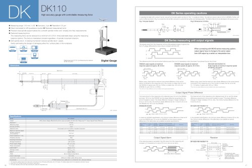
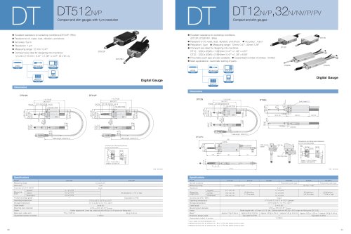
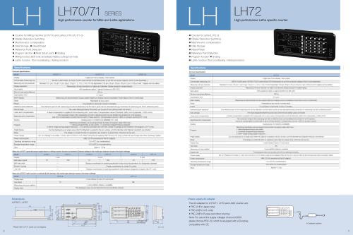
nnnnLH72
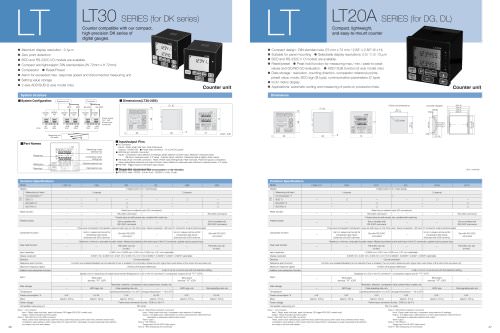
nnnnHigh performance Lathe specific counter.
nnnnCounter for Lathe (LH72-3)
nnnnDisplay Resolution Switching
nnnnMachine error compensation
nnnnData Storage
nnnnReset/Preset
nnnnReference Point Detection
nnnnProgram function • Scaling
nnnnLathe function (Tool coordinating / Adding function)
nnnnSpecifications
nnnnCommon Specifications
nnnnModel | LH72-3 |
Display | 7 digits and minus display, Color amber |
Connectable measuring unit | GB-ER, SJ300 series, SJ700A, PL20C series (Dreof) DG-B (Necessary to use tine conversion adaptor which Is add separately.) |
Measurfrtg unit Input resolution | Standard: 0.1 um, 0.5 um, 1 pm, 5 um, 10pm, 1 s, 10s, 1 mil, 10 min Expanded: 100 pm, 5Onm,25nm,20pm, 2 um, 0.05 pm and 1 degree can be added. |
Display resolution | Measuring unit input resolution or higher and diameter display (except tor angle display) |
Input signal | A/B quadrature signal, Z signal (Conforms to BA-422.) |
Minimum riput phase difference | 100 ns |
Quantization error | ±1 count |
Alarm display | Measuring unit disconnected, Excess speed, Maxrnum display amount exceeded, Power failure, Error in stored data |
Reset | Resettable by key switch or remote reset. |
Preset | It is possible to store/recall 3 kinds of numbers. |
Reference point detection | The reference point of the measuring unit can be detected, and the datum point can be relocated (durirg connection of measuring unit with a reference point) |
Data storage | The value displayed before the power was turned off and setting values are stored |
□near error compensation | A fixed compensation Is appled to the measuring unit's count value. Compensation amount Standard: ±600 um/m (Expanded: ±1000 um/m) |
Segmented error compensation | The movement range of the measuring unit wttti a reference point can be divided Into amaxlmum of 32 sections, and error compensation Is performed for each of these sections. Compensation amount: ±600 um (at each section) |
Scaling | Scaling factor 0,100000 to 9.999999 |
Program | Machining coordinates can be programmed (number of program steps: 850 max.) 1. Manual programming by key switch 2, Automatic programming by playback 3. Mirror Image during program execution |
Angle display | Can be displayed as an angle value when the DlghJer Is pasted to the arc surface, and the diameter and DlghJer resolution are entered |
Sleep | The display is turned off when no operations are made for a preset time. (The time can be set.) |
Display axes | 2-axis display (2-axis or 3-axis hput) |
Tool offset | 99 |
Measuring unit Input addition | 2-axis adcftkxi display is available |
Display hold | The displayed value can be held and the tool coordinate entered. |
Power supply | DC 12 V Rating 0.75 A Max. 1AAC100 V to 240 V ±10% When using the AC adaptor PSC-22 (For U.S. only) or PSC-23 (For Europe and other countries) 'Option |
Power consumption | MAX 32 VA connected at the AC adaptor. |
Operating temperature range | 0 to 40'C (no condensation) |
Storage temperature range | -20 to 6CTC (no condensation) |
Mass | Approx. 1.5 kg |
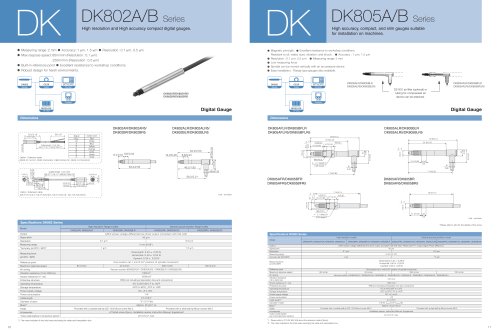
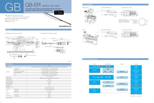
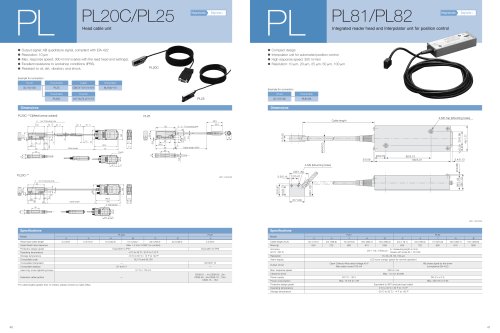
Power supply AC adapter
nnnnThe AC adapter for LH70/71, LH72 and LG20 counter unit.
nnnn• PSC-21 (For Japan only)
nnnn• PSC-22(ForU.S.only)
nnnn• PSC-23(For Europe and other country.)
nnnnNote: For use at the supply voltages of around 200V,
nnnnplease choose PSC-23, which is equipped with a Europlug
nnnncompatible with CE.
nnnn>=4==lrM-c*
nnnnAC adaptor (option)
"