عضویت
عضویت  ورود اعضا
 راهنمای خرید


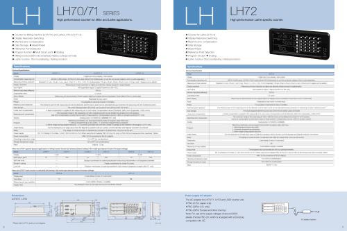
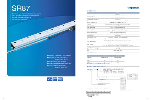
MJ820/8210 pages
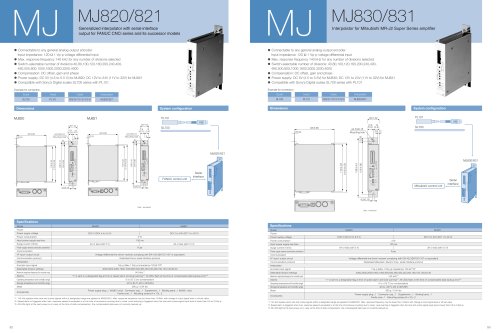
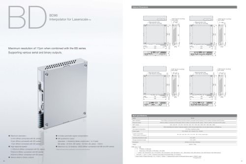
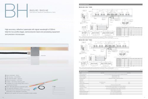
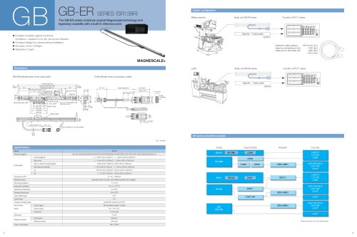
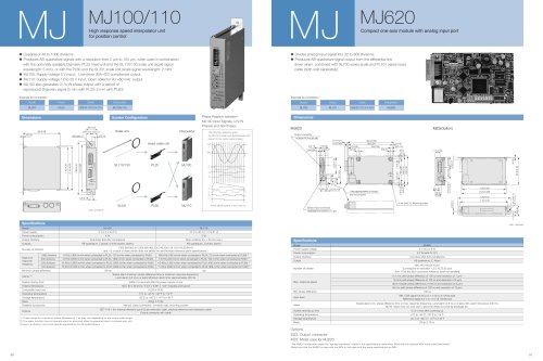
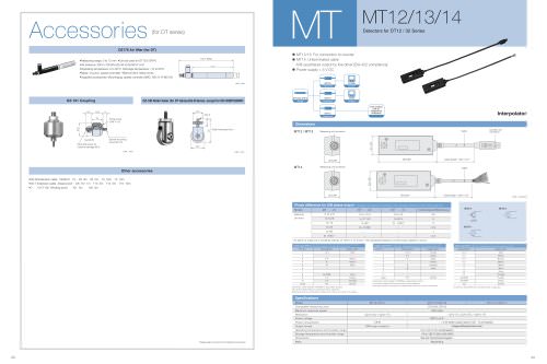
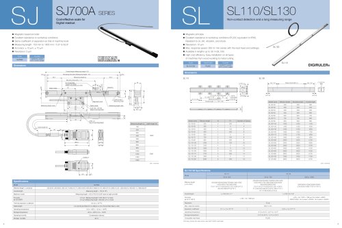
Interpolator for Mitsubishi MR-J2 Super Series amplifier MJ MJ830/831
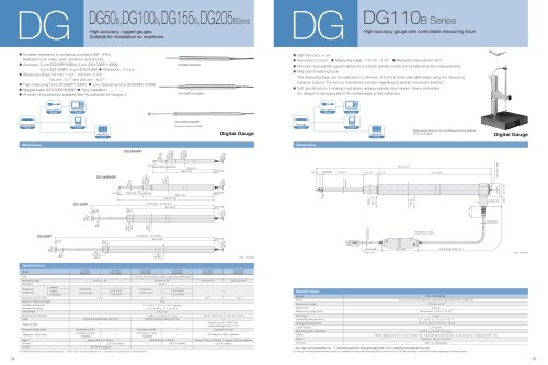
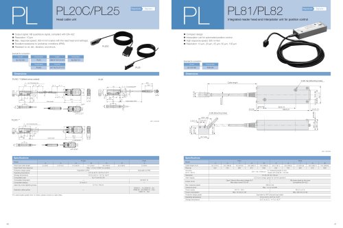
• Connectable to any general analog-output encoder.
Input impedance: 120 Ù 1 Vp-p voltage differential input
• Max. response frequency 140 kHz for any number of divisions selected
• Switch-selectable number of divisions: 40,80,100,120,160,200,240,400,
480,500,800,1000,1600,2000,3200,4000
• Compensation: DC offset, gain and phase
• Power supply: DC 5V (4.5 to 5.5V) for MJ830; DC 12V to 24V (11V to 32V) for MJ831
• Compatible with Sony’s Digital scales SL700 series with PL101
SL700 PL101 MJ830/831
Scale Head Interpolator
Example for connection
CE08 CK-T12/13/14/15/16
Cable
MJ830/831
PL101
SL700
Serial
interface
Mitsubishi control unit
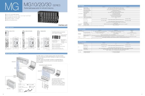
Dimensions System configuration
Model MJ830 MJ831
3 W
100 ms
Fuse
Voltage-differential line driver/ receiver complying with EIA-422 (SN75C1167 or equivalent)
Dedicated Mitsubishi Electric Corp. serial interface protocol
1Vp-p (Max.1.2Vp-p) impedance 120 Ù TYP
4000,3200,2000,1600,1000,800,500,480,400,240,200,160,120,100,64,40
140 kHz*1
"1" is sent to a designated flag at time of speed alarm and level warning*2 All LEDs flash at the time of compensated data backup error*3
0 to +55 °C (no condensation)
-20 to +65 °C (20 to 90%RH)
380 g / 0.84 lbs
Power
Power supply voltage
Power consumption
Input power supply rise time
Surge current (10ms)
Power supply reverse connection prevention
Communication
I/F input/ output circuit
Communication protocol
Interpolator
Encoder input signal
Selectable division settings
Maximum response frequency for encoder input
Alarms
Operating temperature and humidity range
Storage temperature and humidity range
Mass
Specifications
*1: 140 kHz applies when sine and cosine signals within a designated range are applied to MJ820/821. Max. response frequency may be lower than 140kHz with change in input signal level or off-set value.
*2: Speed alarm is triggered when max. response speed is exceeded or at the time of erroneous counting due to noise. Level warning is triggered when the sine and cosine signal input level is lower than 0.6 to 0.5Vp-p.
*3: All LEDs light at the next power-on in case, at the time of data compensation, the compensated data was not correctly backed up.
Accessories
Power supply plug...1 Connector cap...1 Supplement...1 Binding band...1
Ferrite core...1 Mounting screws (4 x 10)...2
DC5 V (DC4.5 to 5.5 V)
4A or less (with 5 V)
DC12 to 24V (DC11 to 32 V)
3A or less (with 12 V)
10
9
8
7
6
5
4
3
2
1
ON OFF
ABS
OFF OFF
ON OFF
OFF ON
ON
LEVEL
SPEED
MJ830
ALM
ON
MADE IN JAPAN
No******
93/3.66
1/0.04
110/4.33
138/5.43
124/4.88
(115)/(4.53)
4.5/0.18
ø4.5/ø0.18
Mounting hole
26/1.02
MODE
(13)
/0.51
13
/0.51
3/0.12
7/0.28
Unit : mm/inch
Unit : mm/inch
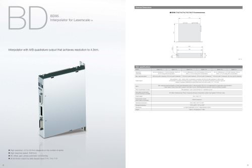
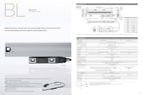
Generalized interpolator with serial-interface
output for FANUC CNCi series and its successor models MJ MJ820/821
• Connectable to any general analog-output encoder.
Input impedance: 120 Ù 1 Vp-p voltage differential input
• Max. response frequency 140 kHz for any number of divisions selected
• Switch-selectable number of divisions:40,80,100,120,160,200,240,400,
480,500,800,1000,1600,2000,3200,4000
• Compensation: DC offset, gain and phase
• Power supply: DC 5V (4.5 to 5.5 V) for MJ820; DC 12V to 24V (11V to 32V) for MJ821
• Compatible with Sony’s Digital scales SL700 series with PL101
SL700 PL101 MJ820/821
Scale Head Interpolator
Example for connection
CE08 CK-T12/13/14/15/16
Cable
MJ820/821
PL101
SL700
Serial
interface
FANUC control unit
Dimensions System configuration
Model MJ820 MJ821
3 W
100 ms
Fuse
Voltage-differential line driver/ receiver complying with EIA-422 (SN75C1167 or equivalent)
Dedicated Fanuc serial interface protocol
1Vp-p (Max.1.2Vp-p) impedance 120 Ù TYP
4000,3200,2000,1600,1000,800,500,480,400,240,200,160,120,100,80,40
140 kHz*1
"1" is sent to a designated flag at time of speed alarm and level warning*2 All LEDs flash at the time of compensated data backup error*3
0 to 55 °C (no condensation)
-20 to 65 °C (20 to 90%RH)
380 g / 0.84 lbs
Power
Power supply voltage
Power consumption
Input power supply rise time
Surge current (10ms)
Power supply reverse connection prevention
Communication
I/F input/ output circuit
Communication protocol
Interpolator
Encoder input signal
Selectable division settings
Maximum response frequency for encoder input
Alarms
Operating temperature and humidity range
Storage temperature and humidity range
Mass
Specifications
*1: 140 kHz applies when sine and cosine signals within a designated range are applied to MJ820/821. Max. response frequency may be lower than 140kHz with change in input signal level or off-set value.
*2: Speed alarm is triggered when max. response speed is exceeded or at the time of erroneous counting due to noise. Level warning is triggered when the sine and cosine signal input level is lower than 0.6 to 0.5Vp-p.
*3: All LEDs light at the next power-on in case, at the time of data compensation, the compensated data was not correctly backed up.
Accessories
Power supply plug...1 (MJ821 only) Connector cap...1 Supplement...1 Binding band...1 (MJ821 only)
Ferrite core...1 Mounting screws (4 x 10)...2
DC5 V (DC4.5 to 5.5 V)
4A or less (with 5 V)
DC12 to 24V (DC11 to 32 V)
3A or less (with 12 V)
3
/0.12
MJ820
10
9
8
7
6
5
4
3
2
1
ON OFF
ABS
OFF OFF
ON OFF
OFF ON
ON
LEVEL
SPEED
MJ820
ALM
ON
MADE IN JAPAN
No******
3
/0.12
93/3.66
1/0.04
110/4.33
138/5.43
124/4.88
(115)/(4.53)
4.5/0.18
ø4.5/ø0.18
Mounting hole
26/1.02
MODE
(13)
/(0.51)
13
/0.51
7/0.28
MJ821
10
9
8
7
6
5
4
3
2
1
ON OFF
ABS
OFF OFF
ON OFF
OFF ON
ON
LEVEL
SPEED
MJ821
ALM
ON
MADE IN JAPAN
No******
1/0.04
MODE
93/3.66
138/5.43
124/4.88
110/4.33
(115)/(4.53)
4.5/0.18
ø4.5/ø0.18
Mounting hole
26/1.02
(13)
/(0.51)
13
/0.51
7/0.28
52 53