عضویت
عضویت  ورود اعضا
 راهنمای خرید


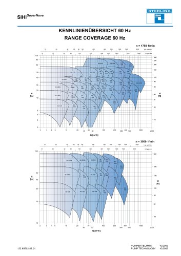
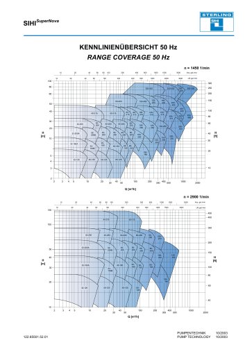
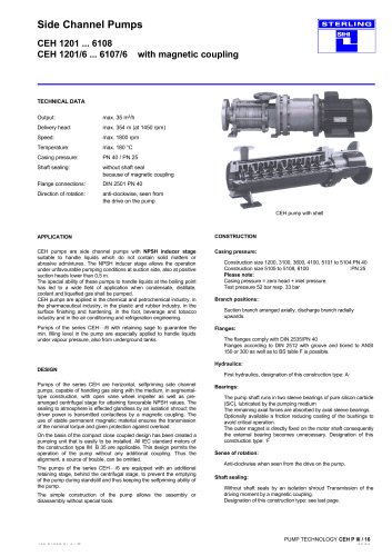
Series MFS, 7,200 m³/h0 pages
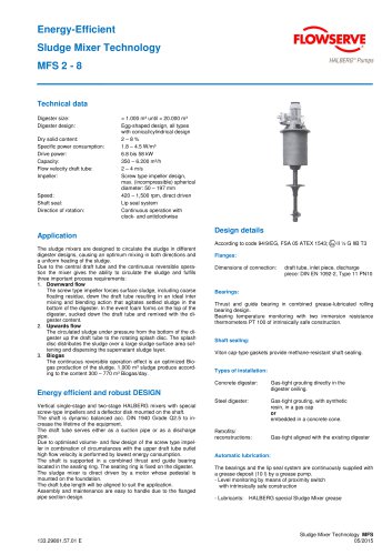
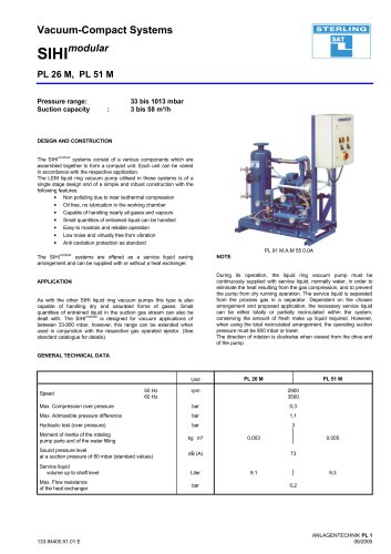
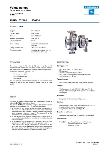
Energy-Efficient
Sludge Mixer Technology
MFS 2 - 8
Technical data
Digester size:
Digester design:
Dry solid content:
Specific power consumption:
Drive power:
Capacity:
Flow velocity draft tube:
Impeller:
Speed:
Shaft seal:
Direction of rotation:
< 1.000 m³ until < 20.000 m³
Egg-shaped design, all types
with conical/cylindrical design
2–8%
1.8 – 4.5 W/m³
6.8 bis 58 kW
350 – 6.200 m³/h
2 – 4 m/s
Screw type impeller design,
max. (incompressible) spherical
diameter: 50 – 197 mm
420 – 1,500 rpm, direct driven
Lip seal system
Continuous operation with
clock- and anticlockwise
Application
Design details
According to code 94/9/EG, FSA 05 ATEX 1543;
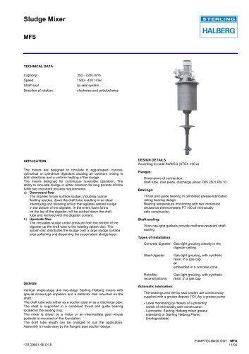
The sludge mixers are designed to circulate the sludge in different
digester designs, causing an optimum mixing in both directions and
a uniform heating of the sludge.
Due to the central draft tube and the continuous reversible operation the mixer gives the ability to circulate the sludge and fulfils
three important process requirements:
1. Downward flow
The screw type impeller forces surface sludge, including coarse
floating residue, down the draft tube resulting in an ideal inter
mixing and blending action that agitates settled sludge in the
bottom of the digester. In the event foam forms on the top of the
digester, sucked down the draft tube and remixed with the digester content.
2. Upwards flow
The circulated sludge under pressure from the bottom of the digester up the draft tube to the rotating splash disc. The splash
disc distributes the sludge over a large sludge surface area softening and dispersing the supernatant sludge layer.
3. Biogas
The continuous reversible operation effect is an optimized Biogas production of the sludge. 1,000 m³ sludge produce according to the content 300 – 770 m³ Biogas/day.
II ½ G IIB T3
Flanges:
Dimensions of connection:
draft tube, inlet piece, discharge
piece: DIN EN 1092-2, Type 11 PN10
Bearings:
Thrust and guide bearing in combined grease-lubricated rolling
bearing design.
Bearing temperature monitoring with two immersion resistance
thermometers PT 100 of intrinsically safe construction.
Shaft sealing:
Viton cap-type gaskets provide methane-resistant shaft sealing.
Types of installation:
Concrete digester:
Gas-tight grouting directly in the
digester ceiling.
Steel digester:
Gas-tight grouting, with synthetic
resin, in a gas cap
or
embedded in a concrete cone.
Energy efficient and robust DESIGN
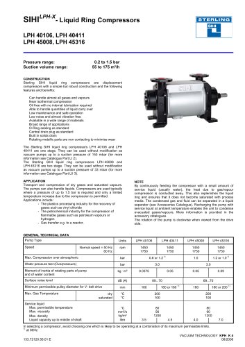
Vertical single-stage and two-stage HALBERG mixers with special
screw-type impellers and a deflector disk mounted on the shaft.
The shaft is dynamic balanced acc. DIN 1940 Grade Q2.5 to increase the lifetime of the equipment.
The draft tube serves either as a suction pipe or as a discharge
pipe.
Due to optimised volume- and flow design of the screw type impeller in combination of circumstances with the upper draft tube outlet
high flow velocity is performed by lowest energy consumption.
The shaft is supported in a combined thrust and guide bearing
located in the seating ring. The seating ring is fixed on the digester.
The sludge mixer is direct driven by a motor whose pedestal is
mounted on the foundation.
The draft tube length will be aligned to suit the application.
Assembly and maintenance are easy to handle due to the flanged
pipe section design.
133.29801.57.01 E
Retrofits/
reconstructions:
Gas-tight aligned with the existing digester
Automatic lubrication:
The bearings and the lip seal system are continuously supplied with
a grease deposit (10 l) by a grease pump.
- Level monitoring by means of proximity switch
with intrinsically safe construction
- Lubricants: HALBERG special Sludge Mixer grease
Sludge Mixer Technology MFS
05/2015