عضویت
عضویت  ورود اعضا
 راهنمای خرید


VD58C5210 pages
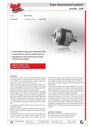
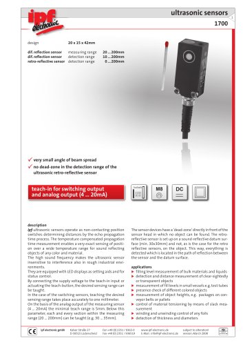
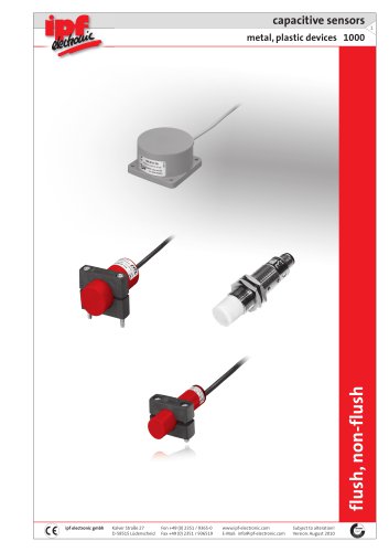
linear measurement systems
encoder 1200
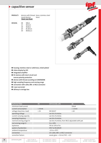
design
Ø58 x 78mm
incremental
number of pulses
30 to 5000
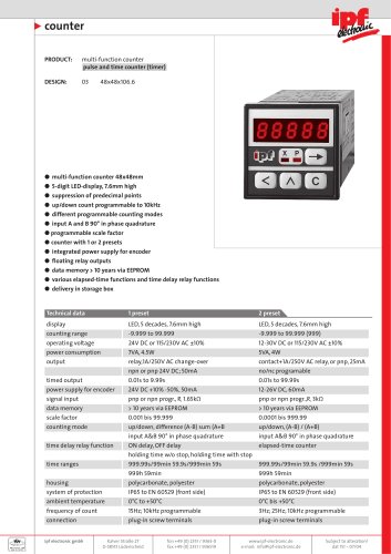
compensation of ageing and temperature drift
compensation in case of a soiled encoder disc
high signal-to-noise ratio thanks to complementary output signals
angular, linear and
speed measurement
description
Incremental encoders are used to detect angle of rotation
and rotary speeds. To measure length or position, connect
the encoder to a driveshaft using a flexible coupling or
directly by way of a friction wheel or pinion.
When measuring length using incremental encoders, the
square wave signals, emitted by the encoder on its signal
lines, are counted. The resolution can be influenced by selecting the number of encoder pulses per rotation.
Incremental encoders operate using photoelectric scanning.
Infrared light that is emitted by a temperature controlled
LED passes through a mask and a code disc and produces a
light proportional DC signal on the optical diodes. When the
shaft turns, periodic signals, similar to sine waves, result on
the optical diodes. The number of signal periods per rotation corresponds to the number of markings on the encoder
disc.
To increase immunity to interference each channel is scanned differentially.
A light-intensity controller compensates both for the temperature and/or ageing drift and for any soiling of the glass
encoder disc.
Incremental encoders lose their current measured value
when the control is turned off or after a power failure. In
order to allow an angle position for any given position to
ipf electronic gmbh
Kalver Straße 27
D-58515 Lüdenscheid
be referenced again, a zero pulse is used that is transmitted once per rotation thus providing an absolute marker.
Incremental encoders emit two output signals in 90º phase quadrature thus allowing the direction of rotation to be
determined.
Linking the two square wave signals together with a pulse
edge evaluation allows the number of pulses per rotation
to be quadrupled. To ensure a clear marker is obtained from
the zero pulse even with pulse quadrupling, its pulse width
is one quarter of the period width of one signal.
As the signals from the incremental encoders are counted
during the evaluation, noise pulses on the signal lines are
bound to cause false counts. For this reason special emphasis must be placed on a particularly large signal-to-noise
ratio. In practice the signal-to-noise ratio is doubled by outputting the complementary (i.e. the inverted) pulses on two
different tracks in addition to the pulse signals in phase quadrature.
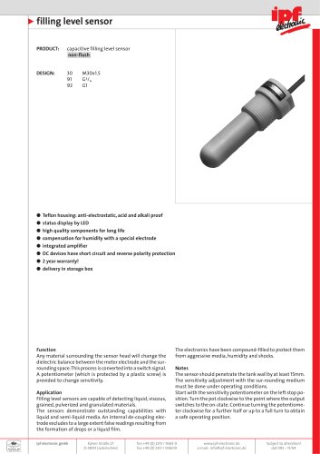
application examples
angular measurement at bending machines
linear measurement at conveyor systems
speed measurement at wind-up units
Fon +49 (0) 2351 / 9365-0
Fax +49 (0) 2351 / 936519
www.ipf-electronic.de
E-Mail: info@ipf-electronic.de
subject to alteration!
Version: June 2009
1
"