عضویت
عضویت  ورود اعضا
 راهنمای خرید


ZM5654530 pages

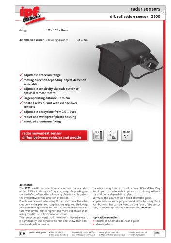
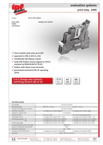
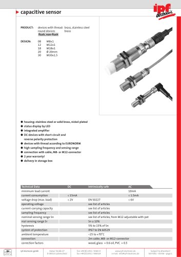
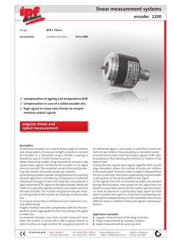
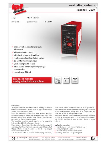
evaluation systems
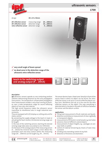
time delay relay 1700
design
22.5 x 75 x 110mm
multi-function
turn-on delay
turn-on delay, instant
turn-on timed
turn-off delay
clocked, starting with pulse
clocked, starting with pause
pulse forming
star/delta switchover
functions and time ranges adjustable
via DIP-switch
large time ranges with high repeat accuracy
2 integrated relays / change-over contacts
remote control via remote potentiometer
wide range power supply
DIN-housing for mounting on DIN-rail
LED function display
multi-function time delay relay
8 functions and time ranges
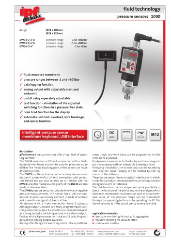
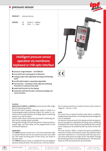
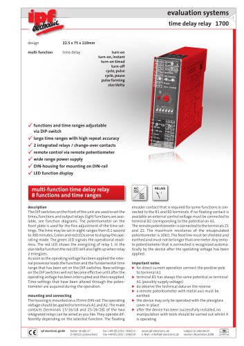
description
The DIP switches on the front of the unit are used to set the
times, functions and output relays. Eight functions are available, see function diagrams. The potentiometer on the
front plate is used for the fine adjustment of the time settings. The time may be set in eight ranges from 0.1 second
to 300 minutes. Green and red LEDs serve to display the operating mode. The green LED signals the operational readiness. The red LED shows the energizing of relay 1. In the
star/delta function the red LED will also light up when relay
2 energizes.
As soon as the operating voltage has been applied the internal processor loads the function and the fundamental time
range that has been set on the DIP-switches. New settings
on the DIP switches will not become effective until after the
operating voltage has been interrupted and then reapplied.
Time-settings that have been altered through the potentiometer are acquired during the operation.
The housing is mounted on a 35mm DIN-rail. The operating
voltage should be applied to terminals A1 and A2. The make
contacts (terminals) of the two integrated relays can be
wired as you like. They operate differently depending on the
ipf electronic gmbh
Kalver Straße 27
D-58515 Lüdenscheid
selected function. The floating encoder contact that is required for some functions is connected to the B1 and B2 terminals. If no floating contact is available an external control voltage must be connected to terminal B2 corresponding to the potential on A1.
The remote potentiometer is connected to the terminals Z1
and Z2. Any remote potentiometer that is connected is
recognized automatically by the device after the operating
voltage has been applied.
The maximum resistance of the encapsulated potentiometer is 10kΩ. The feed line must be shielded and earthed
and must not be longer than one meter.
important notes
automatic run-up controls for motors
lighting controls
fan controls
traffic light controls
elevator and escalator controls
time-controlled processes
precisely-timed operation
Fon +49 (0) 2351 / 9365-0
Fax +49 (0) 2351 / 936519
www.ipf-electronic.com
E-Mail: info@ipf-electronic.com
Subject to alteration!
Version: July 2010
1
"