عضویت
عضویت  ورود اعضا
 راهنمای خرید


CY7C1061G, CY7C1061GE: 16 - Mbit (1 M words × 16 bit) Static RAM with Error - Correcting Code (ECC)0 pages
PRELIMINARY
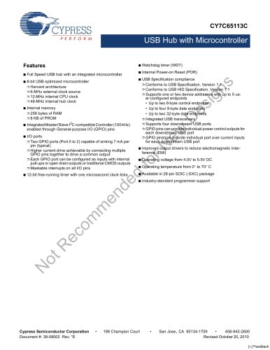
CY7C1061G/CY7C1061GE
16-Mbit (1 M words × 16 bit) Static RAM
with Error-Correcting Code (ECC)
16-Mbit (1 M words × 16 bit) Static RAM with Error-Correcting Code (ECC)
Features
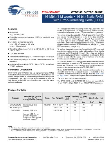
To access devices with a single chip enable input, assert the chip
enable (CE) input LOW. To access dual chip enable devices,
assert both chip enable inputs – CE1 as LOW and CE2 as HIGH.
■
High speed
❐ tAA = 10 ns/15 ns
■
Embedded error-correcting code (ECC) for single-bit error
correction
■
Low active and standby currents
❐ ICC = 90-mA typical at 100 MHz
❐ ISB2 = 20-mA typical
■
Operating voltage range: 1.65 V to 2.2 V, 2.2 V to 3.6 V, and
4.5 V to 5.5 V
■
1.0-V data retention
■
Transistor-transistor logic (TTL) compatible inputs and outputs
■
Error indication (ERR) pin to indicate 1-bit error detection and
correction
■
Available in Pb-free 48-pin TSOP I, 54-pin TSOP II, and 48-ball
VFBGA packages
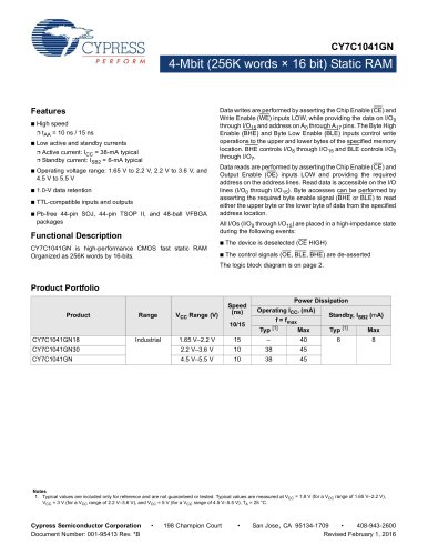
Functional Description
CY7C1061G and CY7C1061GE are high-performance CMOS
fast static RAM devices with embedded ECC[1]. Both devices are
offered in single and dual chip enable options and in multiple pin
configurations. The CY7C1061GE device includes an ERR pin
that signals a single-bit error-detection and correction event
during a read cycle.
To perform data writes, assert the Write Enable (WE) input LOW,
and provide the data and address on the device data pins (I/O0
through I/O15) and address pins (A0 through A19) respectively.
The Byte High and Byte Low Enable (BHE, BLE) inputs control
byte writes, and write data on the corresponding I/O lines to the
memory location specified. BHE controls I/O8 through I/O15 and
BLE controls I/O0 through I/O7.
To perform data reads, assert the Output Enable (OE) input and
provide the required address on the address lines. Read data is
accessible on I/O lines (I/O0 through I/O15). You can perform
byte accesses by asserting the required byte enable signal (BHE
or BLE) to read either the upper byte or the lower byte of data
from the specified address location.
All I/Os (I/O0 through I/O15) are placed in a high-impedance state
when the device is deselected (CE HIGH for a single chip enable
device and CE1 HIGH / CE2 LOW for a dual chip enable device),
or control signals are de-asserted (OE, BLE, BHE).
On the CY7C1061GE devices, the detection and correction of a
single-bit error in the accessed location is indicated by the
assertion of the ERR output (ERR = High). See the Truth Table
on page 16 for a complete description of read and write modes.
The logic block diagrams are on page 2.
The CY7C1061G and CY7C1061GE devices are available in
48-pin TSOP I, 54-pin TSOP II, and 48-ball VFBGA packages.
Product Portfolio
Current Consumption
Product
Features and Options
(see the Pin
Configurations section)
Range
VCC Range (V)
Speed
(ns)
10/15
Operating ICC, (mA)
f = fmax
Standby, ISB2 (mA)
Typ[2]
CY7C1061G18
CY7C1061G(E)30
CY7C1061G
Industrial
Max
Typ[2]
Max
20
30
70
80
10
90
110
4.5 V–5.5 V
Optional ERR pins
15
2.2 V–3.6 V
Single or dual chip
enables
1.65 V–2.2 V
10
90
110
Address MSB A19 pin
placement options
compatible with Cypress
and other vendors
Notes
1. This device does not support automatic write-back on error detection.
2. Typical values are included only for reference and are not guaranteed or tested. Typical values are measured at VCC = 1.8 V (for a VCC range of 1.65 V–2.2 V),
VCC = 3 V (for a VCC range of 2.2 V–3.6 V), and VCC = 5 V (for a VCC range of 4.5 V–5.5 V), TA = 25 °C.
Cypress Semiconductor Corporation
Document Number: 001-81540 Rev. *J
•
198 Champion Court
•
San Jose, CA 95134-1709
•
408-943-2600
Revised June 4, 2014