عضویت
عضویت  ورود اعضا
 راهنمای خرید


AP M600 pages
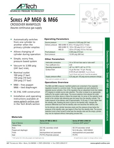
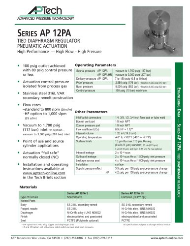
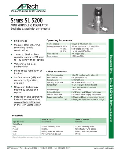
SERIES AP M60 & M66
CROSSOVER MANIFOLDS
Assures continuous gas supply
Operating Parameters
• Automatically switches
from one cylinder to
another when the
primary cylinder empties
cylinder during operation
• Simple, worry free,
Other Parameters
pressure based system
Inlet/outlet connectors
Flow coefficient (Cv)
Operating temperature
Surface finish
Supply pressure effect
• Vacuum to 3,500 psig
(241 bar) inlet,
1/4 or 3/8 inch face seal or tube weld*
0.09
-40° to +160°F (-40° to +71°C)
15 µin Ra max / 10 µin. Ra avg.
(0.4/0.25 µm) standard; 10 µin (0.25 µm);
0.25 psig per 100 psig source pressure change
• Nominal outlet
100 psig (7 bar)
150 psig (10 bar)
250 psig (17 bar)
7 µin (0.18 µm); and 5 µin (0.13 µm) Ra max optional
*Tube weld not available with M60 25.
Operations Overview
• M60 – free poppet
M66 – tied diaphragm
• SS 316L VAR construction
• Installation and operating
instructions available at
www.aptech-online.com
in the Tech Briefs section
The M60 and M66 crossover manifold systems are comprised of two separate
regulators housed in a common body. The two regulators are each attached to
separate source cylinders. One of the regulators has an adjustment knob that rotates
270 degrees to enable source side selection. The other is preset to an appropriate
setting for the system outlet range. The source selection knob adjusts the outlet
pressure to be either above or below the preset side. An arrow on the selection knob
points to the cylinder side delivering gas and away from the standby cylinder. The
outlet pressure of the delivery side is approximately 15-30 psig (1-2 bar) higher than
the standby side. Rotating the knob to point to the standby side, changes the
pressure differential such that the standby side now becomes the delivery side.
As the delivery side cylinder becomes empty and the pressure drops below the
pressure of the standby side, gas begins to flow from the standby side. The source
selection knob is then turned to what was the standby side and the empty cylinder
may now be replaced without interrupting process flow.
Materials
Type of Service
Wetted Parts
Body
Poppet and diaphragm
Finish
Seat
Series AP M60 & M66 S
Noncorrosive
Series AP M60 & M66 SH
Corrosive (SHP option)**
SS 316L secondary remelt
SS 316
electropolished and passivated
PCTFE (Polyimide optional)
ENGINEERING DATA — SERIES AP M60 AND M66 CROSSOVER MANIFOLDS
• Allows changing of
Source pressure
vacuum to 3,500 psig (241 bar)
Delivery pressure M60 & M66 10 85 to 115 psig (5.8 to 7.9 bar)
M60 & M66 15 135 to 165 psig (9.3 to 11.4 bar)
M60 25
225 to 275 psig (15.5 to 19.0 bar)
Proof pressure
4,500 psig (310 bar)
Burst pressure
10,000 psig (690 bar)
SS 316 secondary remelt
Ni-Cr-Mo alloy / UNS N06022
electropolished and passivated
PCTFE
**SHP option Ni-Cr-Mo alloy poppet and diaphragm only.
687 TECHNOLOGY WAY NAPA, CA 94558 • (707) 259-0102 • FAX (707) 259-0117
**All specifications subject to change without notice.
www.aptech-online.com
"