عضویت
عضویت  ورود اعضا
 راهنمای خرید


EVO® Combination Cradle0 pages
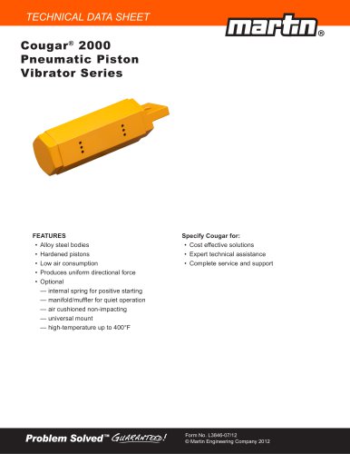
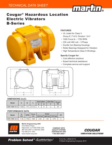
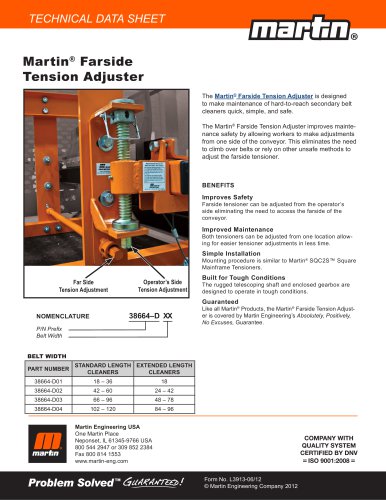
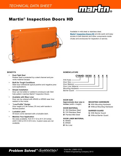
TECHNICAL DATA SHEET
EVO® Combination Cradle
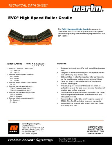
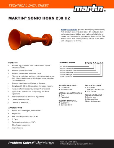
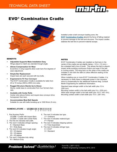
Installed under a belt conveyor loading zone, the
EVO® Combination Cradles absorb the force of falling material
to prevent damage to the belt and structure. The impact cradles
stabilize the belt line to prevent material escape.
BENEFITS
NOTES
•t
Adjustable Supports Make Installation Easy
Wings adjust to match any standard trough angle.
•t
Allows Compensation for Wear
Eccentrics in wing supports allow outer bars five degrees of
wear adjustment.
•t
Simple Bar Replacement
Impact bars are each secured with two bolts.
•t
Engineered to Fit Your Conveyor
The EVO® Combination Cradle is available for belts from
24 to 72 inches (500 to 2000 mm) wide.
•t
Rugged Structure Stands Up to Abuse
Sturdy cradle base is constructed from four formed channels.
•t
Available with Center Rolls
Center rolls reduce friction and require less conveyor drive
horsepower than bars.
•t
Accommodates Most Belt Speeds
Suitable for use with belts traveling up to 1000 ft/min (5 m/s).
EVO® Combination Cradles are installed so that bars in the
center of the cradle are set slightly below—1/2 in. (13 mm)—
the unloaded belt’s line of travel. This allows the belt to absorb
impact while avoiding continuous friction and wear if the belt
is running empty. The wing bars on the sides of the cradle are
installed in line with the idlers to allow effective sealing of the
transfer point.
When installing one or more EVO® Combination Cradles, it is
necessary to verify there is adequate power in the conveyor
drive to compensate for the additional frictional drag. Consult
Martin Engineering for additional information.
Standard base stringer width is the belt width plus 12 in.
(305 mm).
Mounting centers width is the belt width plus 9 in. (229 mm).
Wide base stringer width is the belt width plus 18 in. (457 mm).
Mounting centers width is belt width plus 15 in. (381 mm).
NOMENCLATURE — UCGBX-XX X XX X X X X X
1
2
3
1. Part Number Prefix:
t
UCGBB = Cradle with Impact Bars
UCGBR = Cradle with Center Rolls
2. The first XX indicates belt width.
3. The next X indicates stringer spacing:
t
S = Standard Base
t
W = Wide Base
4. The next XX indicates trough angle:
t
20 = 20 degree
35 = 35 degree
45 = 45 degree
5. The next X indicates duty rating:
t
M = Medium-Duty
4 5 6 7 8 9
6.
t
7.
t
8.
t
9.
t
t
The next X indicates bar type:
U = Urethane
The next X indicates material type:
P = Painted
The next X indicates shipping options:
A = Fully Assembled
The next X indicates stringer type:
E = EVO®
S = Standard
Form No. L8888-88/11 L3971-12/13
Form No.
© Martin Engineering Company 1944, 2011 2012, 2013
© Martin Engineering Company