عضویت
عضویت  ورود اعضا
 راهنمای خرید


Transmission Spheres0 pages
Transmission
Spheres
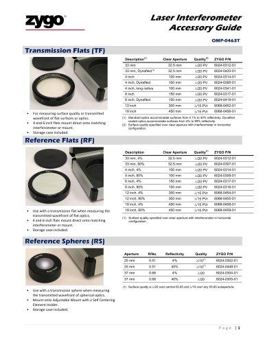
A complete offering of high quality transmission spheres (TS)
designed to provide optimum interferometer performance. ZYGO’s
optics are specified and fully qualified to ensure accurate metrology
for applications ranging from testing conventionally polished ultra
smooth surfaces, to providing critical metrology feedback for small
tool polishing processes. Each TS comes in a protective storage
case with quality certification.
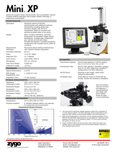
OVERVIEW
Measurement
Capability
Used in conjunction with a laser Fizeau
interferometer for the measurement of the
surface form or transmitted wavefront of
spherical optics and assemblies. Can also be
utilized in the measurement of conic and
aspheric shapes(1).
Diameters
25 mm, 4 inch, 6 inch
ULTRASPHERE (λ/50) TS
Wavelength
633 nm
Specifications
Apply to advertised TS f/#
The UltraSphere is designed to enable surface form metrology with
an uncertainty in the RMS(2) of ≤ 3.2 nm (λ/200 at 633 nm) when
used with a ZYGO interferometer.
Best for metrology of test optics with ≤ 40% reflectivity.
Design
Low expansion reference element.
Field coverage and residual axial ghosts are
suitable for use with ZYGO Ring-of-Fire
illumination.
STANDARD PERFORMANCE (λ/10) TS
Best for metrology of test optics with ≤ 40% reflectivity.
4 inch (101.6 mm)
f/# (4 inch)
f/0.75, f/1.5, f/3.3
Reference Surface
4% reflectivity
λ/50 PVr(3) (λ = 633 nm)
< 2.5 nm RMSi(4)
Reference Surface
Power Spectral
Density (PSD)(5)
Mean Radial Profiles: < 5x10⁴∙freq-1.55 A2µm
Azimuthal Profiles: < 1x10⁵∙freq-1.55 A2µm
Transmitted
Wavefront Slope
Controlled mid-spatial frequency content
(PSD). Suitable for use in closed-loop
feedback processes in work cells utilizing
small pad polishing technologies.
Entrance Beam
Diameter
Supports < 2 nm RMS cavity induced error(6)
Entrance Beam
Diameter
25 mm
4 inch (101.6 mm)
6 inch (152.4 mm)
f/# (25 mm)
f/0.58, f/0.7, f/1.0
f/# (4 inch)
f/0.65, f/0.75, f/1.5, f/3.3, f/7.1, f/10.7
The UltraSphere TS products include absolute calibration of the
reference surface and are shipped with the resulting MetroPro *.dat
file and 37 term Zernike fit on a USB memory stick.
f/# (6 inch)
f/0.8, f/1.1, f/2.2, f/3.5, f/5.4, f/7.2
ADDITIONAL INFORMATION
Reference Surface
4% reflectivity
λ/10 PV (λ = 633 nm)
To dynamically determine the recommenced TS for an application
use the Transmission Sphere Selection Tool, OMP-0495 or the
VeriFire Asphere Calculator Tool, OMP-0525.
Reference Drawings 6024-0034-02 and 6024-0048-02 provide
mechanical dimensions of 4 inch and 6 inch TS’s, respectively.
STANDARD PERFORMANCE DYNAFLECT™ (λ/10) TS
Best for metrology of test optics with > 40% reflectivity.
Entrance Beam
Diameter
4 inch (101.6 mm)
Notations
f/# (4 inch)
f/0.75, f/1.5, f/3.3, f/7.1, f/10.7
Reference Surface
Dynaflect coating
λ/10 PV (λ = 633 nm)
1. Direct measurement of an asphere with a spherical reference wavefront
will introduce retrace errors. A ZYGO VeriFire Asphere interferometer
minimizes retrace by measuring null zones of the asphere that match the
f/# of the transmission sphere.
HIGH PERFORMANCE (λ/20) TS
Best for metrology of test optics with ≤ 40% reflectivity.
Entrance Beam
Diameter
4 inch (101.6 mm)
f/# (4 inch)
f/0.65, f/0.75, f/1.5, f/3.3, f/7.1, f/10.7
f/# (6 inch)
f/0.8, f/1.1, f/2.2, f/3.5, f/5.4, f/7.2
Reference Surface
4% reflectivity
λ/20 PV (λ = 633 nm)
Zygo Corporation
Laurel Brook Road
Middlefield, CT 06455
2. Assumes form metrology of smooth spherical surfaces, a well-nulled
cavity, data averaging to minimize systematic noise, a suitably stable
environment, and uncertainty estimation following ISO’s “Guide to the
Expression of Uncertainty in Measurement” (1995) with k=1.
3. PVr is defined as the 36 term Zernike fit plus 3 times the rms residual of
the Zernike fit (PVr = PV36 Zernike + 3 x σ36 Zernike Residual) .
4. RMSi is the irregularity after removing the best fit spherical surface per
ISO 10110 part 5 (1996)/ISO 14999 Part 4 (2007) standards.
5. Spatial frequency band: 3/Clear Aperture to 0.2/Lateral Scale. PSD limits
defined by the power law model of ISO 10110-8.
6. As-built TS wavefront slope is controlled to insure that the peak cavity
induced retrace errors will contribute less than the specified RMS value up
to reference-to-part radius ratios of 5:1. As an example, a 5:1 ratio for an
f/0.75 TS corresponds to a reference surface of radius 48.2 mm and a test
sphere of radius 9.64 mm. Cavities that yield ratios of > 5:1 may induce
error that exceed the specified RMS.
Phone: 860-347-8506
Email: inquire@zygo.com
Website: www.zygo.com
SS-0043 09/10
© 2010 Zygo Corporation