عضویت
عضویت  ورود اعضا
 راهنمای خرید


Model 5964D High Performance Metal Sealed Mass Flow Controller0 pages
1
Data Sheet
DS-TMF-5964-MFC-eng
October, 2008
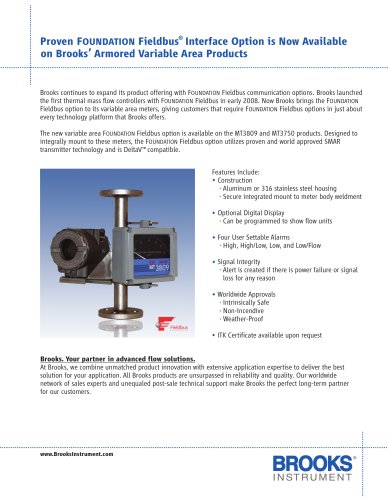
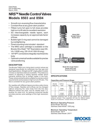
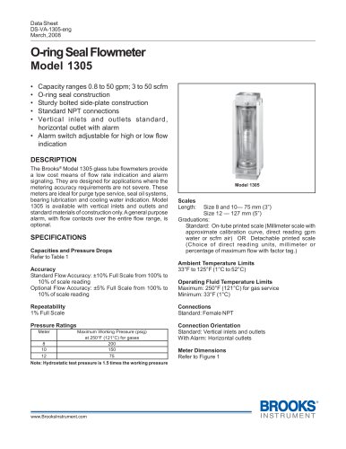
High Performance Metal Sealed MFC
Model 5964D
High Performance Metal Sealed Mass Flow Controller
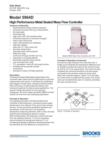
Model 5964D Mass Flow Controller with VCR
Features and Benefits
• Electropolished wetted surfaces (optional)
• Enhanced process (5 Ra avg.) internal finish
• All metal seals
• Particulate free
• High purity VAR 316L stainless steel
• Enhanced response to command changes
• Helium leak check ports
• Class 100 assembly and calibration
• High leak integrity
(less than 10-10 atm-cc/sec He)
• Normally Closed Valve
(Normally Open Valve optional)
• Wide flow range
(0.06 sccm through 30,000 sccm N2)
• Insensitive to mounting attitude
• Electrically activated valve override
• Low command flow cutoff
• TTL compatible "valve off" and purge function
• Available with all popular process
connections
• Downport C-Seal or W-Seal (optional)
Description
The Brooks® Model 5964 Metal Sealed Mass Flow
Controller offers state of the art performance in gas flow
measurement and control. It combines the outstanding
leak integrity of metal seals, ultraclean internal surface
finish (5 Ra avg.) for particulate-free delivery and
enhanced response for rapid process applications. The
superior design also allows for very rapid gas
changeover. All of this makes the Model 5964D the best
solution for even the most challenging application.
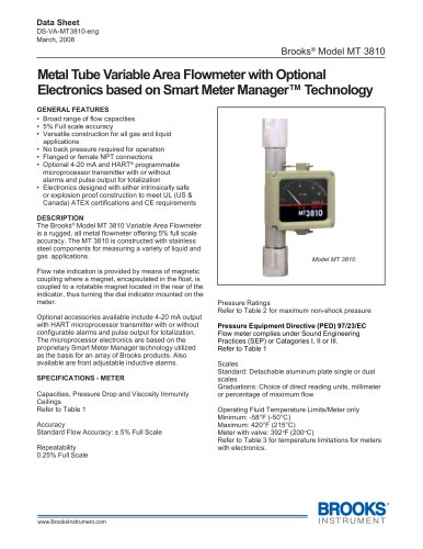
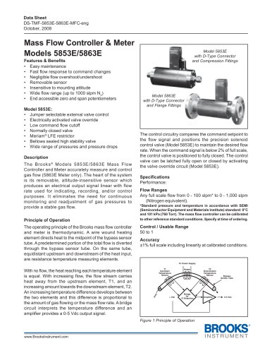
Principle of Operation
The operating principle of the Brooks Mass Flow
Controller is thermodynamic. A precision power supply
directs heat to the midpoint of the sensor tube carrying
the flow. On the same tube equidistant upstream and
downstream of the heat input, are resistance
temperature measuring elements. With no flow, the heat
reaching each temperature element is equal.
With increasing flow, the flowstream carries heat away
from the upstream element, T1 and an increasing
amount towards the downstream element T2. An
increasing temperature difference develops between the
two elements and this difference is proportional to
Principle of Operation (continued)
the amount of gas flowing or the mass flow rate. A
bridge circuit interprets the temperature difference and
an amplifier provides the output to the control circuitry
as well as a 0-5 Vdc output signal. The control circuitry
compares the command set-point to the flow signal
and positions the precision solenoid control valve.
When the command signal is below 1% of full scale,
the control valve is positioned fully closed. The control
valve can be latched fully open or closed by activating
the valve override circuit.
Figure 1 Principle of Operation
± 15 Vdc
Flow
Amplifier
Heater
0-5 Vdc
Bypass
Sensor Tube
T2
Downstream
Temperature
Sensor
To Power Supply
T1
Upstream
Temperature
Sensor
Bridge
for
ÄT Detection