عضویت
عضویت  ورود اعضا
 راهنمای خرید


QLR0 pages
84
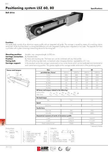
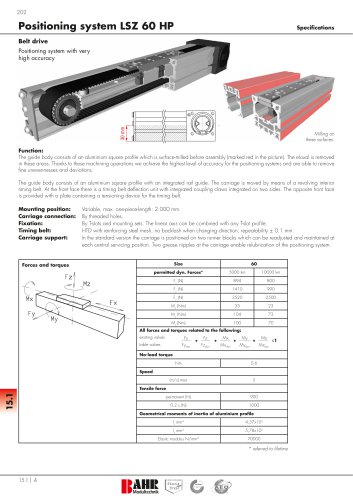
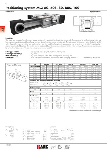
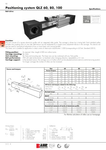
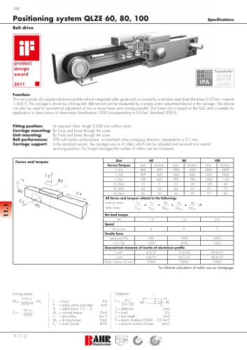
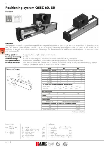
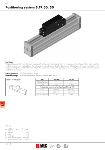
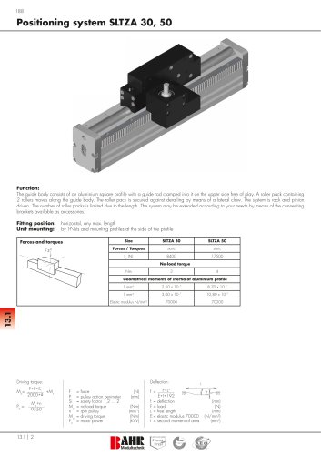
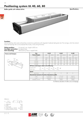
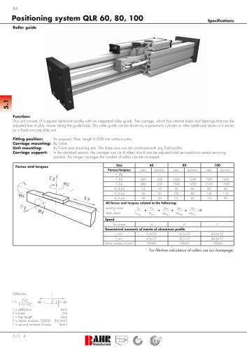
Positioning system QLR 60, 80, 100
Specifications
5.1
Roller guide
Function:
This unit consists of a square aluminium profile with an integrated roller guide. The carriage, which has internal linear ball bearings that can be
adjusted free of play, moves along the guide body. This roller guide can be driven by a pneumatic cylinder or other additional drives or it serves
as a load carrying slide unit.
Fitting position:
Carriage mounting:
Unit mounting:
Carriage support:
As required. Max. length 6.000 mm without joints.
By T-slots.
By T-slots and mounting sets. The linear axis can be combined with any T-slot profile.
In the standard version, the carriage runs on 4 rollers which can be adjusted and serviced at a central servicing
position. For longer carriages the number of rollers can be increased.
Size
Forces and torques
60
80
100
Forces/torques
Fz
static
dynamic
static
dynamic
static
Fx (N)
-
-
-
-
-
-
Fy (N)
600
500
1600
1240
1900
1500
1700
Mz
dynamic
Mx
Fz (N)
Fx
Fy
900
650
1500
1200
2100
Mx (Nm)
15
10
50
40
85
60
My (Nm)
60
50
100
80
140
110
Mz (Nm)
40
30
75
60
110
90
All forces and torques related to the following:
existing values
My
table values
Fy
Fydyn
+
Fz
+
Fzdyn
Mx
Mxdyn
+
My
Mydyn
+
Mz
Mzdyn
≤1
Speed
(m/s) max
4
6
7
Geometrical moments of inertia of aluminium profile
lx mm4
4,3x10⁵
16,5x10⁵
43,0x10⁵
ly mm
4,8x10
18,7x10
48,8x10⁵
Elastic modulus N/mm²
70000
70000
70000
4
5
5
For life-time calculation of rollers use our homepage.
Deflection:
f=
F*L
E*I*192
f =
F=
L=
E=
I =
deflection
load
free length
elastic modulus 70000
second moment of area
3
5.1 | 4
(mm)
(N)
(mm)
(N/mm