عضویت
عضویت  ورود اعضا
 راهنمای خرید


Axis motions controllers type Z-ME-KZ0 pages
www.atos.com
Table G340-6/E
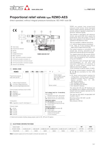
Digital position controllers type Z-ME-KZ
Eurocard format, for electrohydraulic closed loop controls
MAIN FUNCTIONS AND FEATURES
USER INTERFACE
SUPPLY 24V
POSITION REFERENCE
ESC
ENT
UP
DWN
X1
X2
O1
O2
O3
O4
O5
O6
O7
A3
A4
A5
POSITION FEEDBACK
Position
control
Alternated
control
Real-time
fieldbus
Serial port
FORCE FEEDBACK
AUXILIARY INPUT
Internal
reference
DRIVER’S COMMAND
Enhanced
diagnostic
OUTPUTS
I1
I2
I3
I4
I5
I6
I7
I8
A1
A2
P/Q
RS232
INPUTS
FORCE REFERENCE
OK
MONITOR
PROFIBUS
Z-ME-KZ
AUXILIARY OUTPUT
Z-ME-KZ
Z-SW-PS
programming software
1
Z-SW-PS
MODEL CODE
Z - ME
-
KZ
-
PS
/
**
/
**
/
*
Electronic axis controller
in Eurocard format
Electrical Features:
• 4 digits front panel display to check and
change parameters as well as for diagnostics
• Front panel DB9 connector for serial programming interface
• Front panel test points for debug and
maintenance
• Eurocard format (DIN 41494 - Plug-in-units)
• CE mark according to EMC directive
Set code
Alternated position / force
(or position / pressure) control module
Series number
Serial communication interface for configuration
and monitoring function
2
SW
-PS
Software Features:
• Internal generation of motion cycle
• Setting of axis’s dynamic response (PID) to
optimize the application performances
• Software selectable range of electronic
reference analog inputs: voltage or current
• Enhanced diagnostics of the axis status
• Intuitive graphic interface
• In field firmware update through standard
serial communication
• Internal oscilloscope function
Optional fieldbus communication interfaces:
- = standard without fieldbus interface
BC = CANopen communication interface
BP = PROFIBUS DP communication interface
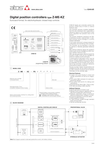
BLOCK DIAGRAM
DIGITAL CONTROLLER Z-ME-KZ
SETPOINT
GENERATOR
POSITION CONTROL
INT
FIELDBUS NETWORK
PROPORTIONAL VALVE
SERIAL PORT
Z-SW-PS
SOFTWARE
PID
EXT
FIELDBUS
FORCE CONTROL
M
I
N
PID
MONITOR
DIGITAL I/O
MACHINE
CENTRAL
UNIT
Z-ME-KZ digital axis controllers perform the
position closed loop of linear or rotative
hydraulic axes.
The controller receives a position feedback
from the axis transducer and it generates a
reference signal to the proportional valve
which regulates the hydraulic flow to the
actuator.
The position feedback interfaces are SSI,
incremental encoder, potentiometer or standard analog inputs (voltage or current)
software selectable.
A front panel serial port is always present for
configuration and monitoring of the controller.
The controller can be operated in real time
by external or internally generated reference
signal.
With external reference signal the actuator’s
motion cycle can be managed by either analog or fieldbus reference input.
With internally generated reference signal the
actuator’s motion cycle can be managed by
external or fieldbus on/off commands.
A pressure/force alternated control may be
set by software additionally to the position
control: a pressure/force transducer has to
be assembled into the actuator and connected to the controller; a second reference
pressure/force signal is required.
Several auxiliary digital inputs/outputs are
available and they can be used to synchronize other machine functions and to transmit
information on the controller state.
FORCE / PRESSURE FEEDBACK
POSITION FEEDBACK
HYDRAULIC ACTUATOR
Note: Block diagram example for alternated position/force control, with fieldbus interface.
G340
"