عضویت
عضویت  ورود اعضا
 راهنمای خرید


Stateflow0 pages
Stateflow
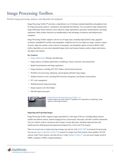
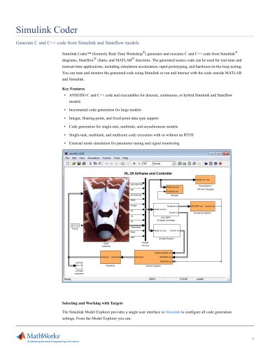
Design and simulate state machines
Stateflow® is an environment for modeling and simulating combinatorial and sequential decision logic based on
state machines and flow charts. Stateflow lets you combine graphical and tabular representations, including state
transition diagrams, flow charts, state transition tables, and truth tables, to model how your system reacts to
events, time-based conditions, and external input signals.
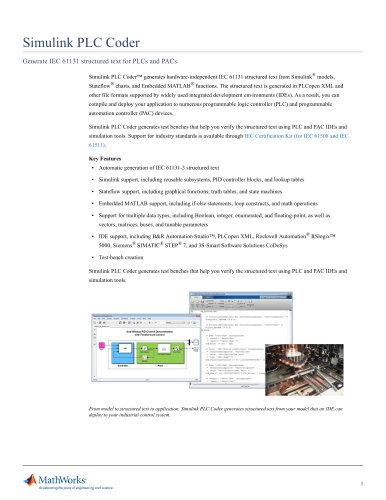
With Stateflow you can design logic for supervisory control, task scheduling, and fault management applications.
Stateflow includes state diagram animation and static and run-time checks for testing design consistency and
completeness before implementation.
Key Features
▪ Modeling environment, graphical components, and simulation engine for modeling and simulating complex
logic
▪ Deterministic execution semantics with hierarchy, parallelism, temporal operators, and events
▪ State diagrams, state transition tables, and state transition matrices representing finite state machines
▪ Flow charts, MATLAB functions, and truth tables for representing algorithms
▪ State diagram animation, state activity logging, data logging, and integrated debugging for analyzing the
design and detecting run-time errors
▪ Static and run-time checks for transition conflicts, cyclic problems, state inconsistencies, data-range
violations, and overflow conditions
▪ Mealy and Moore finite-state machines
Getting Started with Stateflow 3:25
Learn to build and simulate a state machine.
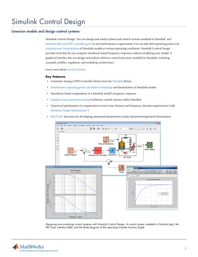
Designing Logic
Stateflow provides graphical and tabular interfaces for modeling system logic using state machines. In a state
machine, you model the system’s modes of operation as states and represent the logic for switching between
modes using transitions and junctions. You can model the different components in your system as states that
execute exclusively or in parallel. Stateflow lets you manage the complexity of your design by organizing state
diagram objects, functions, and components hierarchically.
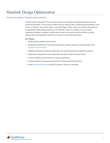
In Stateflow you can represent combinatorial logic graphically with flow charts and in tabular format with truth
tables.
Designing logic involves defining conditions to be checked and subsequent actions to be performed. Stateflow
enables you to define conditions and actions in C or in MATLAB®. You can manage the data used in conditions
and actions from the Simulink® Model Explorer. Before executing your design, Stateflow notifies you of possible
state inconsistencies, unused data and events, and invalid transitions.
1
"