عضویت
عضویت  ورود اعضا
 راهنمای خرید


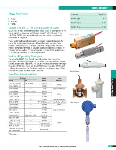
31IS / 32IS Series Pressure Transducers0 pages
31IS Series and 32IS Heavy Duty Series
Intrinsically Safe Industrial Pressure Transmitters
II 1G
Deutsch DT04-4P
t Ex II 1G; Ex ia IIB T4 Ga
t The 3XIS series is certified Instrinsically Safe for use in Group IIB
Hazardous Areas, Zones 0, 1 and 2
t Certification: ATEX Certificate Baseefa10ATEX0196
For OEMs that need intrinsically safe pressure sensors with consistent high levels
of performance, reliability and stability, the 31/32IS Series sputtered thin film units
offer an unbeatable price performance ratio in a small package size. They feature all
stainless steel wetted parts, a broad selection of electrical and pressure connections
and a wide choice of electrical outputs.
Our manufacturing process includes the latest automated equipment, producing
consistent sensor performance.
DIN 9.4 mm
M12 x 1P
Additionally the 32IS Series transmitters feature a thicker diaphragm and a pressure
restrictor to withstand the rigors of cavitation or extreme pressure spikes, delivering
years of reliable and stable performance in pulsating applications.
Packard MetriPack
The compact construction of both these series makes them ideal for installation where
space is at a premium.
These transmitters are also fully RoHS compliant.
Specifications
PRESSURE TRANSDUCERS
Performance
Long Term Drift
Accuracy
Thermal Error
t31IS
t32IS
Compensated Temperatures
Operating Temperatures
Zero Tolerance, Max.
Span Tolerance, Max.
Fatigue Life
Mechanical Configuration
Pressure Port
Wetted Parts
Electrical Connection
Enclosure
Vibration
t
Shock
Approvals
t
t
t
Weight
0.2% FS/YR (non-cumulative)
0.25% FS
Cable
±1.5% max, ±1% typical / 212°F (100°C)
±2% max
-4°F to +176°F (-20°C to +80°C)
-40°F to +176°F (-40°C to +80°C)
0.5% of span
0.5% of span
Designed for more than 100 M cycles
See under “How to Order,” last page
17-4 PH Stainless Steel
See under “How to Order,” last page
IP67 (IP65 for electrical code G)
BSEN 60068-2-6 (FC) Sine (20G)
BSEN 60068-2-64 (FH) Random (14.1 Grms)
BSEN 60068-2-27 (Ea) (50G, 11ms)
Ex II 1G; Ex ia IIB T4 Ga,
-40°F ≤ Ta ≤ +176°F (-40°C ≤ Ta ≤ +80°C)
When used in conjunction with a Zener safety barrier or
Galvanic Isolation barrier
1.8 to 5.3 ounces (50-150 grams). Configuration dependant
EMC Specifications
Emissions Tests: EN61326-1:2006 and EN61326-2-3:2006
EN55011:2007
Radiated Emissions:t
30-230MHz 30dB µV/M @10M
t
t
230-1000MHz 37dB µV/M @10M
Immunity Tests: EN61326-1:2006 and EN61326-2-3:2006
EN61000-4-2:2009
Electrostatic Discharge:t ±4Kv contact
t
t
±8Kv air
EN61000-4-3:2006
Radiated Immunity:t
10V/M 80-1000MHz
t
t
3V/M 1400-2000MHz
t
t
1V/M 2000-2700MHz
EN61000-4-4:2004
Fast Transients:t
±0.25, 0.5, 1Kv
EN61000-4-6:2007
Conducted Immunity:t 3V 0.15 to 80MHz 80% 1KHz modulation
H-40
Amp
Superseal 1.5
Conduit
Large DIN
Individual Specifications
Voltage
Output (3-wire)
t
Supply Voltage
Source and Sinks
Current
Output (2-wire)
Supply Voltage
t
Maximum Loop
Resistance
Ratiometric
Output
t
Supply Voltage
Visit www.GemsSensors.com for most current information.
0V min. to 10V max.
See under “How to Order,” last page
1
Volt above full scale to 30V max @
4.5 mA
2 mA
4-20 mA
8-24 Volts measured at the input to
the transducer terminals
(Supply Voltage – 8) x 50ohms
See Graph
0.5 to 4.5V
(Source and sink 2mA)
5 Vdc ±10% @ 4.5mA
31IS-32IS Series / p1of4 / 11-SEP-14