عضویت
عضویت  ورود اعضا
 راهنمای خرید


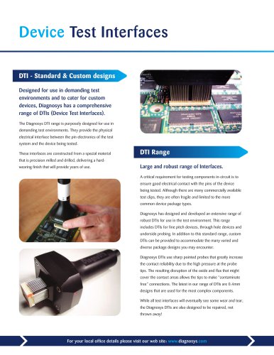
AutoPoint DT0 pages
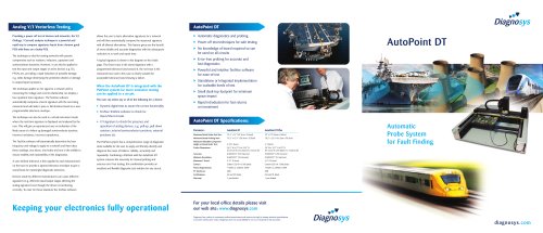
Analog V/l Vectorless Testing
nnnnProviding a power-off test of devices and networks, the V/l
nnnn(Voltage / Current) analysis technique is a powerful and
nnnnrapid way to compare signatures learnt from a known good
nnnnPCB with those on a faulty PCB.
nnnnThe technique is ideal for testing networks with passive
nnnncomponents such as resistors, inductors, capacitors and
nnnnsemiconductor junctions. However, it can also be applied to
nnnntest the input and output stages of active devices e.g. ICs,
nnnnFPGAs etc. providing a rapid indication of possible damage
nnnne.g. static damage destroying the protection diodes or damage
nnnnto output/input transistors.
nnnnThe technique applies an AC signal to a network and by
nnnnmeasuring the voltage and current relationship can display a
nnnnfour quadrant trace signature. The TestVue software
nnnnautomatically compares a learnt signature with the one being
nnnnmeasured and will make a pass or fail decision based on a user
nnnnprogrammable tolerance envelope.
nnnnThe technique can also be used in a virtual instrument mode
nnnnwhere the real-time signature is displayed and analysed by the
nnnnuser. This will give an experienced user an indication of the
nnnnlikely cause of a failure eg damaged semiconductor junction,
nnnnincorrect resistance, incorrect capacitance.
nnnnThe TestVue software will automatically determine the best
nnnnfrequency and voltage to apply to a network and then takes
nnnnthree readings, one above, one below and one in the middle to
nnnnensure stability and repeatability of the diagnostics.
nnnnA user defined tolerance is then applied to each measurement
nnnnon the trace to provide a tapered tolerance envelope to give a
nnnnsound basis for meaningful diagnostic decisions.
nnnnDevices made by different manufacturers can cause different
nnnnsignatures (e.g. different input/output stages affecting the
nnnnanalog signature) even though the device is functioning
nnnncorrectly. To cater for these situations the TestVue software
nnnnallows the user to learn alternative signatures for a network
nnnnand will then automatically compare the measured signature
nnnnwith all allowed alternatives. This feature gives you the benefit
nnnnof more reliable and accurate diagnostics with the subsequent
nnnnreduction in re-work and repair time.
nnnnA typical signature is shown in the diagram on the inside
nnnnpage. The Green trace is the stored signature with a
nnnnprogrammed tolerance band around it, the red trace is the
nnnnmeasured trace and in this case is clearly outside the
nnnnacceptable tolerance band showing a failure.
nnnnWhen the AutoPoint DT is integrated with the
nnnnPinPoint system far more extensive testing
nnnncan be applied to a circuit.
nnnnThe user can select any or all of the following for a device:
nnnn► Dynamic digital tests to assure the correct functionality
nnnn► TestVue TrakTest software to check for
nnnnOpen/Short circuits
nnnn► V/l signature to check the presence and
nnnnoperation of analog devices, e.g. pull-up, pull-down
nnnnresistors, internal semiconductor junctions, external
nnnnjunctions etc
nnnnThe PinPoint system has a comprehensive range of diagnostic
nnnntools available for the user to apply and thereby identify and
nnnndiagnose the cause of failures, reliably, accurately and
nnnnrepeatedly. Combining a PinPoint with the AutoPoint DT
nnnnsystem removes the necessity for manual probing and
nnnnensures error free testing; this combination provides an
nnnnexcellent and flexible diagnostic test solution for any circuit.
nnnnKeeping your electronics fully operational
nnnnAutoPoint DT
nnnn► Automatic diagnostics and probing
nnnn► Power-off test techniques for safe testing
nnnn► No knowledge of board required so can
nnnnbe used on all circuits
nnnn► Error-free probing for accurate and
nnnnfast diagnostics
nnnn► Powerful and intuitive TestVue software
nnnnfor ease-of-use
nnnn► Standalone or Integrated implementation
nnnnfor scaleable levels of test
nnnnSmall desk-top footprint for minimum
nnnnspace impact
nnnn► Rapid introduction for fast returns
nnnnon investment
nnnnAutoPoint DT Specifications:
nnnn- V
nnnn1
nnnnDiagnosys
nnnnAutoPoint DT
nnnnMil
nnnn■
nnnniá
nnnnParameter;
nnnnAutoPoint DT
nnnnAutoPoint DT Plus
nnnnMaximum Board-Under-Test Size:
nnnnMaximum Board-Probing Area:
nnnnMaximum Allowable Component
nnnnHeight on Board Under Test:
nnnnProber Dimensions:
nnnnAccuracy:
nnnnMinimum Resolution:
nnnnMaximum Z Travel:
nnnnCamera:
nnnnPower Requirements:
nnnnPC Interfaces:
nnnnCertifications:
nnnnWarranty:
nnnn19.4" X 14" (49.3cm X 35.6cm)
nnnn15.3" x 12.9 " (38.9cm x 33.8cm)
nnnn2.375" (6cm)
nnnn26.5"Wx13"Hx24.5"D
nnnn(67.31 cm W x 33.02cm H x 62.3cm D)
nnnn0.0007874" (±20 microns)
nnnn0.0003937" (10 microns)
nnnn2.21" (5.6cm)
nnnnColour CCD 811 x508 pixels
nnnn115VACor230VAC100W
nnnnUSB
nnnnCE and ETL listed
nnnn1 year limited
nnnn22"x23" (56cm x 58cm)
nnnn18.2" x 22.4" (46.2cm x 56.9cm)
nnnn4" (10cm)
nnnn36"Wx15.7"Hx29"D
nnnn(91.44cm W x 39.88cm H x 73.66cm D)
nnnn0.0007874" (±20 microns)
nnnn0.0003937" (10 microns)
nnnn4.2" (10.6cm)
nnnnColour CCD 811 x508 pixels
nnnn115VACor230VAC100W
nnnnUSB
nnnnCE and ETL listed
nnnn1 year limited
nnnnAutomatic
nnnnProbe System
nnnnfor Fault Finding
nnnnFor your local office details please visit
nnnnour web site: www.diagnosys.com
nnnnDiagnosys has a policy of continuous product improvement and reserves the right to change technical specifications
nnnnat any time without prior notice. Diagnosys does not accept liability for errors or misprints in this document.
nnnnDiagnosys
nnnndiagnosys.com
"