عضویت
عضویت  ورود اعضا
 راهنمای خرید


MSA 710, MSA 8100 pages

www.rsf.at
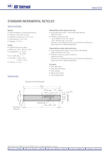
MSA 710, MSA 810
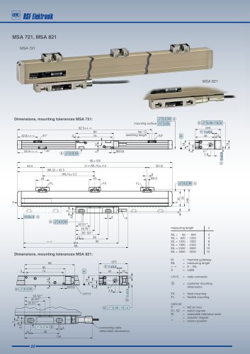
Dimensions, mounting tolerances MSA 710:
50+«M
5.5 ±5
40+<
30+^. ^S1*
-Rl*
5.5
40 ±20
90
80
74
// 0.2 M
Ira
typ-12.
switching length
S2*
M4T6
ML+105
ML+94 ±0.4
50 S2"
40 Rl*
.30 sr
mi -<*>
,0±2(K)
J2_
ML
//|0.2|M
56
//|0.05/13|A^
(46)
) 1 ±0.5.
32
24.2
13.
.5.5 ±5
-//|O.2|M|®
CJ 10.03 mounting
surface
// 0.2 M
65 ±20
4,8
8.8
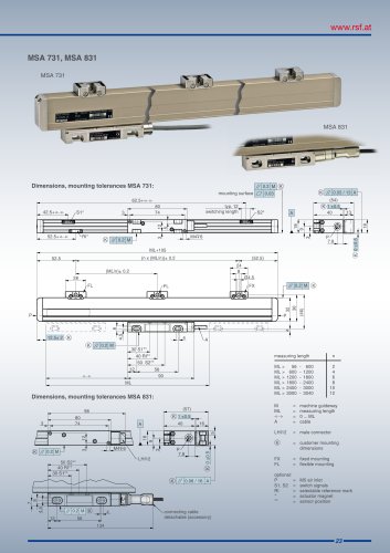
Dimensions, mounting tolerances MSA 810:
98
,_80_
74
o
®|//|O.2|MH
40 Rl*' 30 S1" |
50 S2*
// 0.2 Ml
56
M456
134
// 0.06/16 A
J49L
) 1 ±0.5
16
-LHI12
d
-connecting cable
detachable (accessory)
M = machine guideway
ML = measuring length
G = gauging points
<M> = 0...ML
A = cable
LHI12 = male connector
® = required mating dimensions
optional:
P = M5 air inlet
S1, S2 = switch signals
Rl = selectable reference mark
= actuator magnet
= sensor position
"