عضویت
عضویت  ورود اعضا
 راهنمای خرید


From 2D-3D CAD to FEM Analysis - The Development of an Application at RKB0 pages

FROM 2D/3D CAD TO FEM ANALYSIS: THE DEVELOPMENT OF AN APPLICATION AT
RKB
RKB TECHNICAL REVIEW - APRIL 2010
1
From 2D/3D CAD to FEM Analysis:
the Development of an Application at RKB
Ciprian Radu, Catalin Danaila
RKB Bearing Industries - Advanced Software Engineering Unit
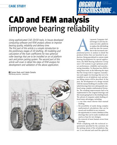
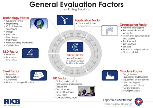
Abstract: RKB Bearing Industries produces a wide range of bearings of different size, but most
of all it is specialized in manufacturing custom-made bearings for special applications. In this
paper, the development of an oil platform will be followed to make clear how the transition
from handmade 2D paper sketch to CAD design has led to an overall enhancement of the
quality, performance, reliability and delivery time of our bearings. We will show how 2D/3D
CAD tools and FEM analysis software are used to study the behavior of the bearings required
by specific applications, providing customers with the best possible technical solutions.
Key words: Bearing, Design, 2D, 3D, CAD, FEM, Oil platform
1. History
Since the earliest times, the need to draw a plan or a sketch of the things to be
built or manufactured appeared. It is very possible that technical drawings
predated even the written language. The drawing board inscripted with a temple
plan from the city of Lagash in Babylon is the oldest known technical drawing (3rd
millennium B.C.). The ancient Greeks (Euclid, Pythagoras, Thales, Plato, and
Aristotle) had a big contribution on how drawings are made today, with their study
of geometry. One of the oldest examples from the medieval period is the Plan of
Saint Gall (figure 1), which was created somewhere between 819 and 826 A.D. and
depicts an entire Benedictine monastic compound, including churches, houses,
stables, kitchens, workshops, brewery, infirmary, and even a special house for
bloodletting [10].
The contemporary technical drawing has its roots in 15th century, in the
Renaissance Era, with artists like the Italian architect Filippo Brunelleschi, who is the
first to use mathematical perspective to redefine Gothic and Romanesque space
and to establish new rules of proportion and symmetry (figure 2). In the 18th century,
the mathematician Gaspard Monge was the first to use descriptive geometry,
when he drew up a fortification plan that would prevent enemies from seeing or
firing at a military position (figure 3). The isometric drawing was later introduced, in early 19th century, by Englishman
William Farish [11] (figure 4).
Before the 18th century, there was no need for interchangeable parts, the components were selected randomly, so
that they fit together, and there was no accurate drawing for them. All products were made one at a time, which
made each one of them unique. Through the 19th century, many of the designs started with a handmade sketch,
which was then changed into a wooden model before being constructed [10].
One of the first efforts to create a program, standardize drawings and establish a mechanical drawing school,
came from Philadelphia Franklin Institute, in 1824. Architecture was among the first design disciplines that made use
of conventions of plan, elevation and section, in design and production. The higher complexity of the architectural
projects generated a separation between design and construction. The Industrial Revolution pushed engineers to
use architectural conventions [13; 14].
Together with the Industrial Revolution came the mass production of the same part, and designs started to be
made with the interchangeable concept in mind. For this to be accomplished, parts needed to be identical, within
designed tolerances. Naturally, this is possible only with detailed technical drawings of every part of the assembly to
be built. Sometimes the drafting was handmade by the project engineer, but, due to the massive amount of work
that was necessary, this job was usually left in the hands of specialized drafters. The drafters used a smooth surface
Fig. 1 - The Plan of Saint Gall