عضویت
عضویت  ورود اعضا
 راهنمای خرید


RKB Guidelines for Mounting Medium to Large TQO Bearings Poster0 pages
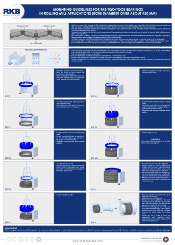
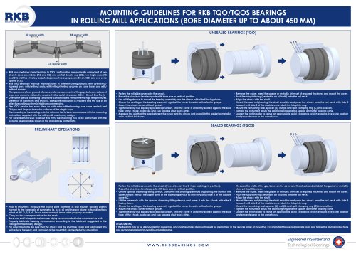
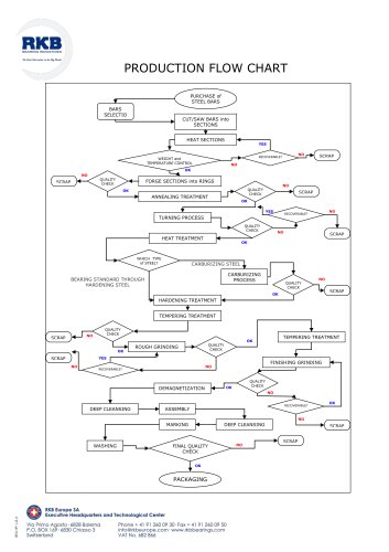
MOUNTING GUIDELINES FOR RKB TQO/TQOS BEARINGS
IN ROLLING MILL APPLICATIONS (BORE DIAMETER OVER ABOUT 450 MM)
DD spacer width
E
D
BB spacer width
D
B
E
C
B
A
C
A
CC spacer width
PRELIMINARY OPERATIONS
1
2
a
b
c
d
3
4
•t RKB four-row taper roller bearings in TQO configuration are generally composed of two double cone assemblies (AC and CE), one central double cup
(BD), two single cups (AB and DE) and three factory adjusted spacers: two cup spacers (BB and DD) and one cone spacer (CC).
•t RKB TQO bearings may be manufactured in different configurations: with cylindrical/tapered bore, with/without seals, with/without helical grooves on
cone bores and with/without spacers.
•t The spacers are face ground after accurate measurements of the gaps between adjacent cups and cones to obtain the required initial axial clearance
(B.E.P. - Bench End Play).
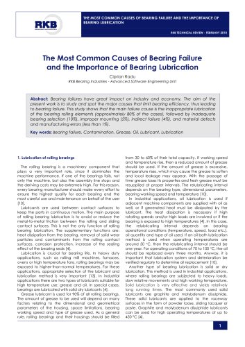
•t Due to the special operating conditions (contaminated environments, high temperatures, presence of vibrations and shocks), adequate lubrication is
required and the use of an effective sealing system is highly recommended.
•t The TQOS version has seals fitted on both sides of the bearing, one cone seal set and O-type seal rings on the outer surfaces of the single cups.
•t The mounting of the bearing onto the roll neck has to be in accordance with the mounting instructions supplied with the rolling mill machinery design.
•t For bore diameters over about 450 mm, the mounting has to be performed with the bearing assembled as shown in the below procedure.
•t Prior to mounting, measure the chock bore diameter in four equally spaced planes normal to the bore axis of symmetry (a, b, c, d) and in each plane
in four directions offset at 45° (1, 2, 3, 4). These measurements have to be properly recorded.
•t Carry out the same procedure for the shaft.
•t Bore and shaft shape deviations are highly recommended to be measured as well.
•t Properly lubricate bearing components according to the lubricant suggested in the rolling mill machinery design.
•t For easy mounting, be sure that the chock and the shaft are clean and lubricated; this will reduce the wear and corrosion of the assembly elements
during operation.
•t Fasten the roll-side cover onto the chock.
•t Place the chock on level supports with
bore axis in vertical position.
•t Place the single cup DE into the chock and
check the seating of the cup against the
cover shoulder with a feeler gauge.
STEP I
•t Add the cup spacer BB, which is provided
with lubrication holes.
STEP VI
•t Add the double cone AC with side C facing
down.
•t Handle the cone with care: do not place it
on (or hang it from) the cage, but only on
(or hang it from) the inner ring.
•t Rotate the cone to seat the rollers in proper
position.
•t Add the cup spacer DD, which is provided
with lubrication holes.
•t Take care not to cause nicks on the chock
bore surface or burrs on the spacer.
STEP II
STEP VII
•t Insert the double cone CE with side E facing
down.
•t Handle the cone with care: do not place it
on (or hang it from) the cage, but only on
(or hang it from) the inner ring.
•t Rotate the cone to seat the rollers in proper
position.
STEP III
•t Add the single cup AB.
WARNING!
All the cups need to be placed so that the
marked zones are aligned.
STEP VIII
•t Add the cone spacer CC.
The cone spacer has a special design with
equally spaced lubrication slots, whose
purpose is to let lubricant go through the
bearing to the roll neck.
G
STEP IV
STEP IX
•t Insert the double cup BD.
CBA
STEP V
•t Mount the chock cover without gasket.
•t Tighten evenly four equally spaced cap
screws, until the cover is uniformly seated
against the side face of the chock, and
cups and cup spacers abut each other.
•t Measure the width of the gap (G) between
the cover and the chock and establish the
gasket or metallic shim set final thickness.
•t Remove the cover, insert the gasket or
metallic shim set of required thickness and
mount the cover.
STEP X
•t Push the labyrinth ring (heated in an oil
bath) onto the roll neck.
•t Align the chock with the shaft.
•t Mount the seal neighboring the shaft
shoulder and push the chock onto the roll
neck with side E forward until side E of the
double cone abuts the labyrinth ring.
•t Mount the remaining seal, spacer (A), nut
(B) and split clamping ring (C) into position.
•t Tighten the nut until it abuts the clamping
ring and the spacer abuts the bearing
cone.
•t Loosen the nut in order to leave an
appropriate axial clearance, which
enables free cone rotation and prevents
wear to the cone faces.
DISMOUNTING
If the bearing has to be dismounted for inspection and maintenance, dismounting will be performed in the reverse order of mounting. It is important to use appropriate tools and follow the above instructions and recommendations to avoid bearing damage.
W W W. R K B B E A R I N G S . C O M
ENGINEERED IN SWITZERLAND
TECHNOLOGICAL BEARINGS