عضویت
عضویت  ورود اعضا
 راهنمای خرید


M-1000 Control Meter0 pages
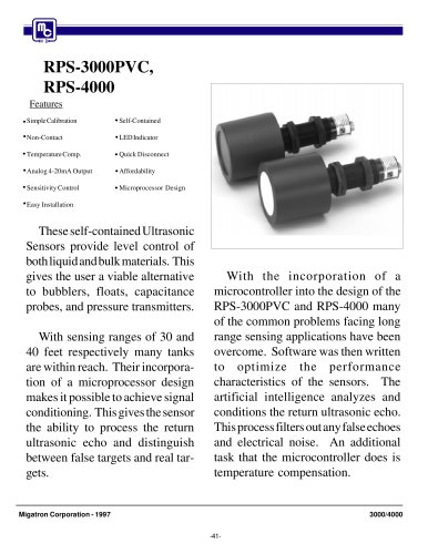
M-1000
Features
Analog Input
Sealed Front Panel (Nema) 4
Dual Sensor Control
Program Lock Access Code
Temp. Compensation
Enclosure 1/8 DIN
Communication Port RS485
Scaling of Display
Thickness Measuring
Power Supply 110 mA at 24 VDC
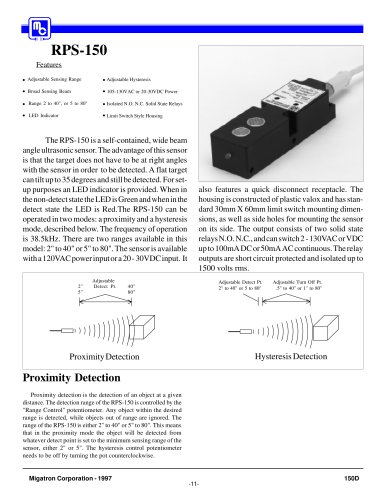
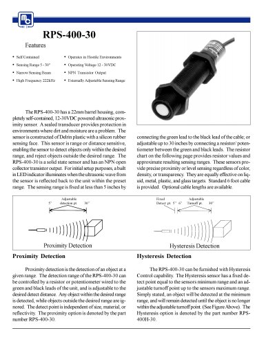
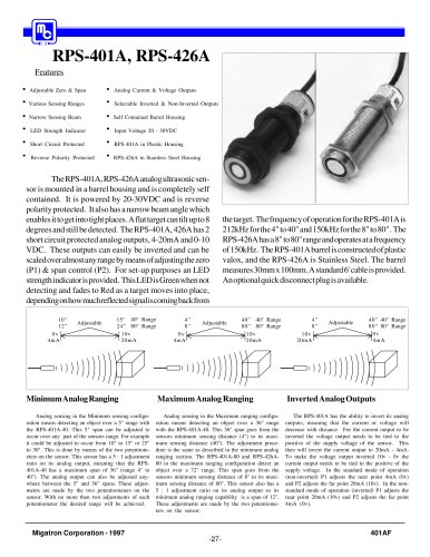
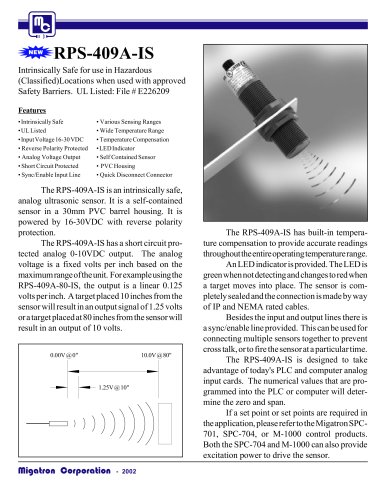
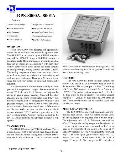
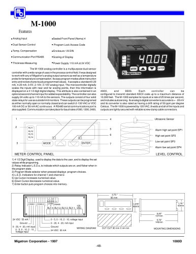
The M-1000 analog controller is a multipurpose dual sensor
controller with a wide range of uses in the process control field. It was designed
to work with any of Migatron's analog output sensors as well as a temperature
probe for temperature compensation. Its easy program modes allow instruction
entry and review of previously programmed values. It accepts a standard 0-20
mA, 4-20 mA, 0-5V, 2-10V, 0-10V analog input. The microcontroller digitally
scales the inputs with near and far scaling points, then this information is
displayed on a 4 1/2 digit digital display. This attribute is also contained in an
optional second channel input for added expandability.The controller can also
supply 24 volts up to 110 mA to the sensors. The outputs consist of four solid
state relays for use as outside limit monitors. These outputs can be programed
as either normally open or normally closed and can switch 2-130 VAC or VDC
100 mA DC or 50 mA AC continuous. A RS485 serial communications port is
also supplied. Communication can take place for baud rates of 300, 1200, 2400,
4800,
and
9600.
Each
controller
can
be
configured to transmit standard ASCII code up to a maximum distance of
10,000 feet. The M-1000 samples its inputs at a rate of 25 times per second,
and includes autozeroing. Its analog to digital converter is accurate to +- .05 mV
and its converter is also rated as having a drift rating of 50 ppm per degree
Celsius. The M-1000 is powered by 120 VAC, 8 watts and all of the inputs and
outputs are tightly secured with reliable screw clamp cable connectors.
1
4
2
5
RLY2
RLY3
RLY4
3
1
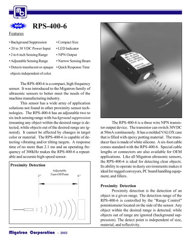
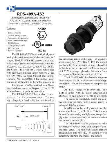
Alarm high set point SP1
6
RLY1
Ultrasonic Sensor
High set point SP2
2
ENTER
MODE
Low set point SP3
7
Alarm low set point SP4
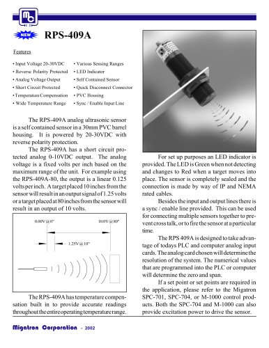
METER CONTROL PANEL
LEVEL CONTROL
1) 4 1/2 Digit Display, used to display the data to the user, and to display the set
values while programing.
2) Relay Indicator L.E.D.s, to indicate which outputs are on, and flicker when in
the program state.
3) Program Mode selector when pressed displays program choices.
4) L.E.D. Indicators for channel 1 and channel 2.
5) Up Cursor increases numerical value.
6) Down Cursor decreases numerical value.
7) Enter button puts program choices into memory.
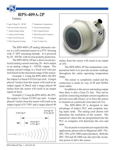
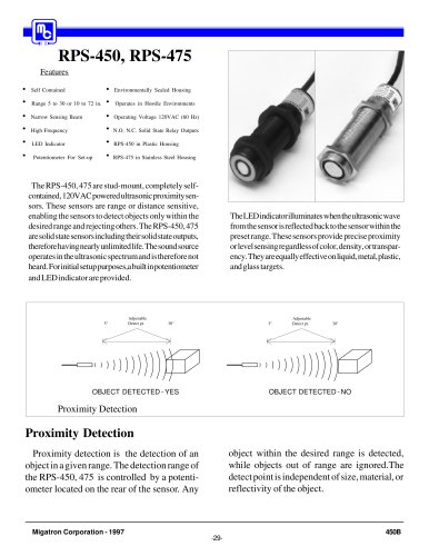
CHAN 1 CHAN 2
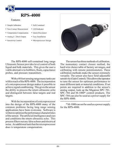
3.75 "
95 mm
+ -- V
24 G IN -- +
CHAN RS485
3
1.70 "
43mm
1.875"
48mm
120
RLY 4 RLY 3 RLY 2 RLY 1 VAC
5.40"
137mm
24 VDC 55 mA
Ground
0 - 20, 4 - 20, mA input
0 - 5, 0 - 10, 2 - 10
Voltage Input
0 - 5, 0 - 10, 2 - 10, voltage input
5.70"
145mm
0 - 20, 4 - 20, mA input
Ground
CUT OUT 90 mm X 44 mm
WIRING DIAGRAM
24 VDC 55 mA
Migatron Corporation - 1997
MOUNTING DIMENSIONS
1000D
-48-