عضویت
عضویت  ورود اعضا
 راهنمای خرید


TBT/TBR-600 Thru-Beam Ultrasonic Sensor0 pages
TBT/TBR-600
Features
•
•
•
•
•
•
Self Contained
Sensing Range 0 - 40"
Operating Voltage 20 - 30VDC
200 counts per Second Maximum
N.O. & N.C. Solid State Outputs
Signal Strength LED Indicator
•
•
•
•
•
•
Used as Thru-Beam or Reflective
Adjustable Delay
Adjustable Count Rate
Adjustable Sensitivity
PVC Housing
Short Circuit Protected
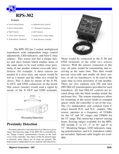
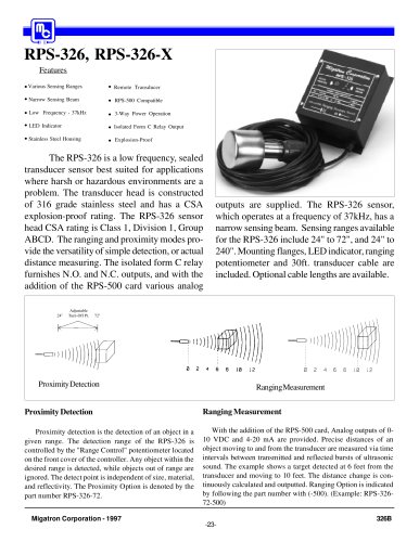
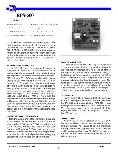
The TBT/TBR-600-40QD is primarily a Thru-Beam
sensor consisting of one transmit and one receive transducer, in separate and self contained housings. It can count
up to 200 objects per second, as they pass through its ultrasonic beam, from 0 - 40". The sensors can also be
mounted in a Reflective position to detect targets. The ThruBeam and Reflective mounting options provide the user with
simple and accurate ways to detect the presence of various
objects. An adjustable Delay control is added to vary the
output response of the solid state relays to the time, or count
rate, of a moving target. An adjustable Sensitivity control
is added to provide highly accurate target detection. P1 on
the receiver (TBR) is labeled sensitivity adjustment. The
LED is provided to show signal strength. The sensor is
factory set with P1 fully clockwise (cw), making the LED
Transmitter
solid red in color. When P1 is fully counterclockwise (ccw),
the LED will be solid green in color. After positioning the
sensors at the required distance, a typical adjustment is performed by turning P1 ccw, causing the LED to change from
a solid red to a mostly red condition. The unit is now properly adjusted. To achieve greater sensitivity for smaller targets, turn P1 ccw so that the LED will be more green in
color. To make the sensors less susceptible to heavy dirt
build up, turn P1 cw so that the LED will be brighter red in
color.
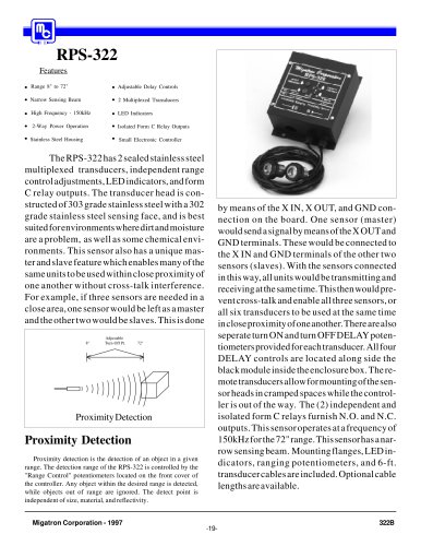
Fixed Detect
Pt. 2"
Receiver
3"
Adjustable turn
off pt
14"
Transmitter
Receiver
Fig. A
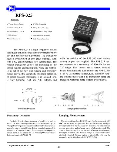
Receiver
Transmitter
Fig. B
Fig. C
Sensitivity
Delay
Thru-Beam/Reflective
Adjustable sensitivity is provided to accurately detect the distance of the target, by use
of the P1 control potentiometer. To adjust, position the sensors in the desired locations. P1 should
be fully counter clockwise, for the minimum sensitivity. In this position the LED will be in the
green, or no detect state. Turn P1 slowly clockwise until the LED changes in color to a red yellow
combination, and remains stable. In this state the
sensors will provide the best detection of the desired target, and will not be affected by an adjacent
target.
Adjustable delay is provided to vary the response
of the solid state relay outputs, in relationship to
time or the count rate of a moving target, by use of
the P2 control potentiometer. P2 fully counter
clockwise provides the fastest response time, and
P2 fully clockwise provides the slowest response
time. See the specification page under Response
Time and/or Count Rate for more detail. The adjustment is performed simply by turning P2,
counter clockwise (faster) or clockwise (slower),
to respond appropriately to the speed of the targets moving past the sensors detection point.
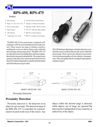
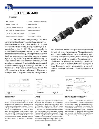
Figure A shows the transmit and receive
sensors mounted for a Thru-Beam application.
Figures B and C show the transmit and receive
sensors mounted for a Reflective application. The
TBT/TBR-600-40QD sensors can be used effectively for both sensing applications. The adjustment procedures for sensitivity, delay, and count
rate, pertain to both the Thru-Beam and Reflective type of mounting or sensing applications.
-34-
"