عضویت
عضویت  ورود اعضا
 راهنمای خرید


Zenith ZBTE Bypass-Isolation Open Transition0 pages
GE Energy
Digital Energy
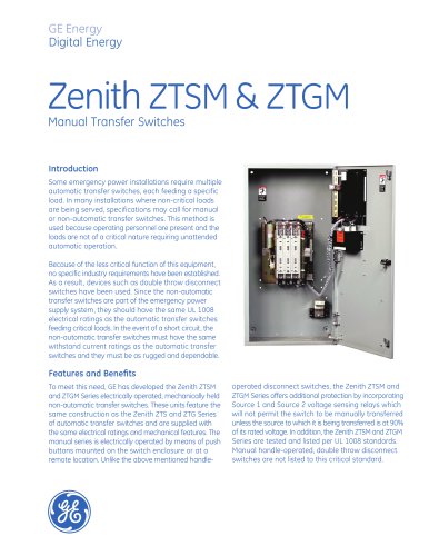
ZBTE
Low-Voltage
Bypass/Isolation Open Transition
Automatic and Manual Transfer Switches
• Ideal for mixed (inductive and resistive) mission critical loads
• Contact transfer speed less than 100 milliseconds
• Bypass/Isolation for ease of ATS maintenance/testing without load loss of power
• Ratings 100 to 4000 amperes
Ratings & Construction
Ratings – Voltage, Ampere and Pole
configuration per Order Code
Certifications – UL 1008, CSA C22.2
Certifications – Third-party Seismic
Certication to IBC 2006, 3.2g @ Ip = 1.5
(operation during event)
Enclosure
Type – per Order Code
Display, Sensing & Time Delays
Display – ¼ VGA color graphical with
embedded ‘HELP’ menus
Electrical Operator – Momentarily energized, high-speed solenoid mechanism
Annunciation – High intensity LED for Source
Availability (2), Source Connected (2), Transfer
Inhibit (not in Auto)
Mechanism – Mechanically-held with
mechanical interlock to inhibit connection
of both sources to the load
Source Fail/Restore – Independently adjustable
pickup & dropout of 3-phase U/O voltage,
U/O Freq, Volts Balance plus Phase Rotation
Contacts – GE design and manufactured,
silver tungsten alloy with separate arcing
contacts on 600A and above ratings for
high withstand and close-on capability
Time Delays – Gen start, Source 2 stabilize,
Source 2 fail override, Retransfer to Source 1,
Gen cool down, Independent settings for Fast
Test, Time Delay for Generator Voltage Sag
Neutral Pole (4 pole only) – Identical construction to phase poles with fully rated main and
arcing contacts. Operation via same mechanism
as phase poles to prevent sustained connection of source neutrals in separately derived
systems, as last-break/first-make transfer.
Remote Access – All parameters locally
(front USB port) or remotely (serial or
Ethernet) Adjustable
Controller
Construction – Dual-processor based, with
dedicated processor for high-speed Serial
or Ethernet communications
Source Sensing – Direct 120-690V sensing
and software configuration of rated voltage
and frequency without the need for potential
transformers, step-down transformers or
DIP switches
Control Wiring – All customer connections at one
location. All signals in/out relay-isolated via DINmounted relay/terminal blocks. All control
wiring via factory-installed wiring harnesses.
Control Group Options (see order code)
Group A: All standard features, Field re-programmable I/O (4 inputs, 4 outputs), Control
Switches (Test with Load, Test no load, Fast Test,
Alarm Reset, Auto/Man Re-transfer Source 1,
Auto/Man Transfer both sources, Preferred
Source select, Commit/No Commit Transfer
to Gen, Time Delay Bypass
Group B: All features from “A” plus: 10 Userconfigurable Analog & 10 Digital Alarms,
20-channel data logger, 10-channel waveform capture, Auto Load Shed (with voltage,
frequency, and kW triggers)
Group C: All features from “B” plus: 4 additional field programmable inputs (total 8
inputs, 8 outputs)
Additional Standard Features
Engine Exerciser – Configurable Periodic
Exerciser (7 Event Daily, Weekly, 14 or 28 day)
or Clock Exerciser Type (21 Event, 365 day
Programmable)
System Status Screen – Active state of switch,
display of all time delays and alarm conditions
Event Recorder – 256 Event, 1ms accuracy,
clock sync via Network Time Protocol (NTP)
Outage & Test Report Screen – Date/time
stamping of: outage or test event, start
signal sent, Gen start time, connection to
Gen, Max Gen Volts & Freq dip, return of
utility, re-transfer to normal
External Power Supply – Standard 120VAC
input for controller power and communication
and 24 VDC input for remote control and
annunciation when both sources de-energized
Flexible Feature Assignment – Field reassignable I/O for any/all control features
In-Phase Monitor – For phase matching
prior to Live-Live transfers of load
Optional Features (see order code)
Serial Communications – High speed, up
to 115k Baud Modbus RTU
Ethernet Communications – Fast Ethernet,
(10/100 Mbit), Modbus TCP/IP
Power Quality Metering – True RMS metering,
including THD% (up to 8th order)
Load Shed – Ability to transfer to de-energized
normal source or center position in event of
generator overload
Integral Surge Protective Device (SPD) –
Load-connected medium or high exposure type
Group D: All features from “C” plus: 4 additional field programmable inputs (total 12
inputs, 12 outputs) & GE Flexlogic™ userconfigurable control logic
Integral Battery Charger – 3 or 10A, 12 or
24VDC type
Group M: Manual ATS configuration
Lugs – Mechanical or Compression lugs in
lieu of standard rear-bus connection on
1600-4000A switches
Lugs – Compression lugs in lieu of standard
mechanical lugs on 100A-1200A switches