عضویت
عضویت  ورود اعضا
 راهنمای خرید


Micro-BDCBB0 pages

PRODUCT OVERVIEW
Micro-BDCBB
DC Battery Distribution Circuit Breaker Bay
Benefits
•t Ideal for customer premise power
applications
Reliability
• t Digital meter interface
–t Delivers decades of service
• t 600 Amp capacity panels in a
compact 4 RU size
–t High availability architecture
–t NEBS level 3 certified
• t Small power distribution from battery
plant to load equipment
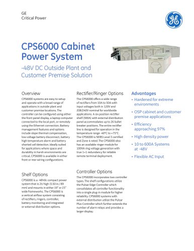
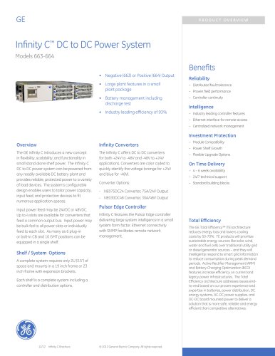
Overview
The GE Micro-BDCBB serves as a secondary
power distribution center for +24Vdc or
-48Vdc DC power delivered from a battery
plant to the load equipment. The 4U (7 in.) tall
configuration is versatile with 19” or 23” rack
or wall mounted panels with fuse or circuit
breakers options, single or dual (A/B) load bus,
and 600A carrying capacity per panel (300A
per bus in dual load bus configurations.) A
digital meter monitors voltage and current of
each load bus.
Fuse / Circuit Breaker Panels
Distribution protector options include:
• t 6 position GMT bullet fuseholder
• t 6 position 0-125A TPS/TLS fuseholder
• t 14 position 0-250A circuit breakers for 19”
wide panels
• t 22 position 0-250A circuit breakers for 23”
wide panels
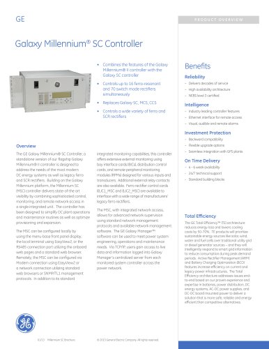
VIM 1 Intelligent Meter
Typical DC distribution panels have a simple
477C alarm card that indicates a breaker/
fuse alarm with a visual red alarm light and
an isolated closure for remote monitoring.
GE provides a digital smart meter for more
extensive monitoring and control. This is the
same smart meter used in the large H569445 BDFB. The VIM 1 monitor, or smart meter,
has an alarm sensitive back-lit display that
changes color from green to red on alarm.
01/13 Micro-BDCBB
Intelligence
–t Industry leading digital smart monitor
–t Network interface for remote access
Current, voltage and alarm information for the
A and B buses are accessed thru the display.
There are three primary alarms:
–t Visual, audible and remote alarms
Investment Protection
Power Loss/Under Voltage: Generates an
–t Backward compatibility
alarm when power is lost to either the A or B
bus; or when a user configurable low voltage
threshold is reached.
–t Flexible upgrade options
–t Seamless integration with GPS plants
On Time Delivery
Overload: Generates an alarm when a user
configurable current threshold is reached. A
configurable time delay may also be set to
avoid nuisance alarms due to bus transients.
–t Standard building blocks
–t 4 - 6 week availability
–t 24/7 technical support
Breaker/Fuse: Generates an alarm when either
a circuit breaker trips or a fuse blows.
The VIM 1 digital meter includes an audible
alarm with a user configurable on/off feature.
There is a form-C relay for each of the three
alarms for remote monitoring - power loss/
under voltage, current overload/threshold
exceeded, and blown fuse/
breaker trip. There are
two RJ45 type connectors
on the board that allow
multiple VIM 1 boards to be
daisy chained together for
network connectivity.
Total Efficiency
Alarm Cable Pinouts and Description
Pin
Form-C Alarm
Wire Color
7
1
2
10
4
5
12
6
11
Fuse NO
Fuse NC
Fuse C
OVL NO
OVL NC
OVL C
PL NO
PL NC
PL C
Blue
White/Blue
Slate
White/Slate
Orange
White/Orange
Yellow
White/Yellow
White
© 2013 General Electric Company. All rights reserved.
The GE Total Efficiency™ (TE) architecture
reduces energy loss and lowers cooling
costs by 50-70%. TE products will prioritize
sustainable energy sources like solar, wind,
water and fuel cells over traditional utility grid
or diesel generator sources – and they will
intelligently respond to smart grid information
to reduce consumption during peak demand
periods. Active Rectifier Management™
(ARM) and Battery Charging Optimization™
(BCO) features increase efficiency on current
and legacy power infrastructures. The Total
Efficiency architecture addresses issues endto-end based on our proven experience and
expertise in batteries, power distribution, DC
energy systems, AC-DC power supplies, and
DC-DC board mounted power to deliver a
solution that is more safe, reliable and energy
efficient than competitive alternatives.