عضویت
عضویت  ورود اعضا
 راهنمای خرید


HC7 Series0 pages

HC7 Series
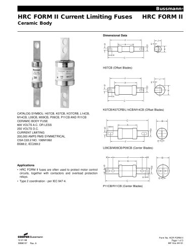
HIGH CURRENT 7
Power Inductors
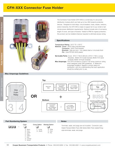
Description
RoHS
2002/95/EC
• 155°C maximum total temperature operation
• Surface mount inductors designed for higher
speed switch mode applications requiring
lower inductance, low voltage and high current
• Design utilizes high temperature powder iron material
with a non-organic binder to eliminate thermal aging
• Inductance range from 0.22 uH to 4.81 uH
• Current range from 35.8 to 9.8 Amps
• Frequency range 1kHz to 500kHz
Applications
• Next generation microprocessors
• High current DC-DC converters
• VRM, multi-phase buck regulator
• PC, Workstations, Routers
• Telecom soft switches, Base Stations
Environmental Data
• Storage temperature range: -40°C to +155°C
• Operating ambient temperature range: -40°C to +155°C
(range is application specific)
• Solder reflow temperature: +260°C max. for 10 seconds
max.
Part
Number
HC7-R20-R
HC7-R47-R
HC7-1R0-R
HC7-1R5-R
HC7-2R2-R
HC7-3R9-R
HC7-4R7-R
Rated
Inductance
µH
.20
.47
1.0
1.5
2.2
3.9
4.7
OCL (1)
nominal
+/-20% µH
0.220
0.534
1.05
1.73
2.58
3.61
4.81
Irms (2)
Amperes
(Typ.)
35.80
23.40
20.30
14.20
13.00
10.40
9.80
Isat (3)
Amperes
15% rolloff
45.8
27.5
19.6
15.3
12.5
10.6
9.2
1) Test Parameters: 100KHz, 1.0Vrms
2) Irms Amperes for approximately ∆T of 40°C above 85°C ambient
3) Isat Amperes Peak for approximately 15% rolloff (@20°C)
4) Isat Amperes Peak for approximately 30% rolloff (@20°C)
5) Applied Volt-Time product (V-µS) across the inductor. This value represents the
applied V-µS at operating frequency necessary to generate additional core loss
which contributes to the 40°C temperature rise. De-rating of the Irms is required
to prevent excessive temperature rise. The 100% V-uS rating is equivalent to a
ripple current Ip-p of 20% of Isat (30% rolloff option).
It is recommended that the temperature of the part not exceed 155°C under worst
case operating conditions verified in the end application.
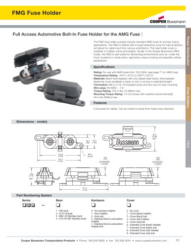
Mechanical Diagrams
C
DCR (mΩ)
max. @
20°C
0.67
1.60
2.10
4.30
5.20
7.90
9.00
Volts (5)
µSec
(VµS)
2.27
3.83
5.36
6.90
8.40
10.0
12.6
Units supplied in tape and reel packaging. 13" reels 610 parts per reel.
Carrier tape width = 24 mm. Meets EIA standard
Part number definition:
HC7-XXX-R
HC7 = Product code and size
XXX = Inductance value in uH.
R = Decimal point. If no R is present, third character = #of zeros
-R suffix indicates RoHS compliant
SIDE VIEW
L
Height
Max
Length
Max
3.0 ± 0.25
(2x)
2.60 m
ax
5.10
±0.40
13.0
Max
RECOMMENDED PCB PAD LAYOUT
3.50 typ
2plcs
SCHEMATIC
1
3.50 typ
2plcs
6.50 typ
wwllyy = Date code R = Revision level
Isat (4)
Amperes
30% rolloff
86.5
51.9
37.1
28.8
23.6
20.0
17.3
FRONT VIEW
TOP VIEW
HC7-XXX
wwllyy R
Packaging
• Supplied in tape and reel packaging, 610 parts per reel
2
Maximum Dimension
Part Number
HC7-R20-R
HC7-R47-R
HC7-1R0-R
HC7-1R5-R
HC7-2R2-R
HC7-3R9-R
HC7-4R7-R
Height mm
6.0
5.5
5.5
5.5
5.5
5.5
5.5
Length mm
14.25
13.8
13.8
13.8
13.8
13.8
13.8
Dimensions in Millimeters.
All dimensions I+/- 0.2 mm unless otherwise specified.
All soldering surfaces are coplanar within 0.15 mm.