عضویت
عضویت  ورود اعضا
 راهنمای خرید


DSIC Single and Dual Axis Rugged Digital Servo Inclinometer0 pages
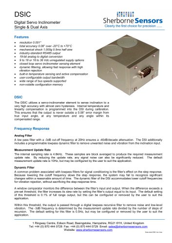
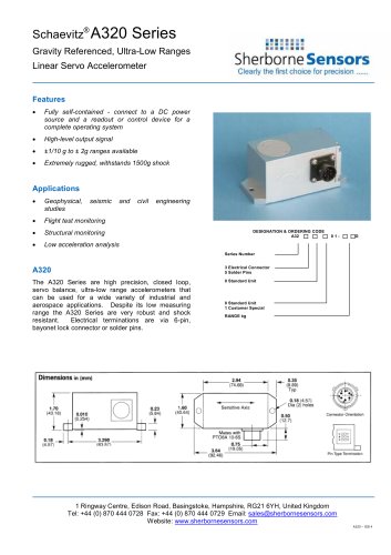
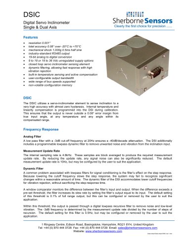
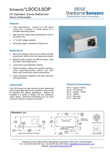
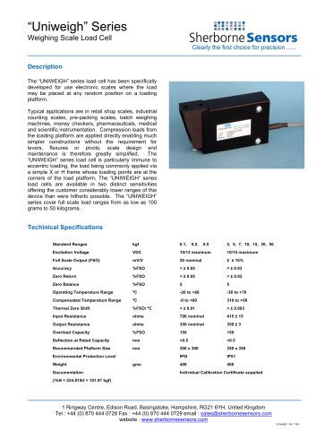
DSIC
Digital Servo Inclinometer
Single & Dual Axis
Features
•
•
•
•
•
•
•
•
•
•
•
•
resolution 0.001°
total accuracy 0.08° over -20°C to +70°C
mechanical shock 1,000g 0.5ms half sine
industry-standard RS485 output
19-bit analog to digital conversion
9 to 18 or 18 to 36 Vdc unregulated supply options
closed loop servo inclinometer sensing element
dynamic filtering, allowing fast response with high
vibration rejection
built-in temperature sensing and active compensation
user-configurable output bandwidth
wide range of bus speeds supported
non-volatile configuration memory
DSIC
The DSIC utilizes a servo-inclinometer element to sense inclination to a
very high accuracy with almost zero hysteresis. Internal temperature and
linearity compensation is programmed into the DSI during calibration.
This ensures that the output is never outside a 0.08° error margin from
true input angle, at any temperature and any angle within its
compensated range.
Frequency Response
Analog Filter
A low pass filter with a -3dB cut-off frequency at 20Hz ensures a -40dB/decade attenuation. The DSI additionally
includes a programmable lowpass dynamic filter to remove unwanted noise and vibration from the inclination input.
Measurement Update Rate
The internal sampling rate is 4.8kHz. These samples are block averaged to produce the required measurement
update rate. By reducing the update rate, any signal noise can also be significantly reduced. The default
measurement update rate is 10Hz, but may be configured by the user to suit the application.
Dynamic Filter
A common problem associated with lowpass filters for signal conditioning is the filter’s effect on the step response.
Because lowering the cutoff frequency slows the step response, the system may fail to recognize significant
changes within a reasonable amount of time. The dynamic filter of the DSI accommodates lower cutoff frequencies
for vibration rejection, without sacrificing the step-response time.
A window comparator monitors the difference between the filter’s input and output. When the difference exceeds a
pre-set threshold, the filter increases its slew rate by setting the filter’s output equal to its input. The default setting
of this threshold is 0.1% of full range output, but this can be configured or removed by the user to suit the
application.
Within this threshold, the output is passed through a digital lowpass recursive filter to remove noise and low-level
vibration. The -3dB frequency is determined by the measurement update rate divided by the number of steps of
recursion. The default setting for this filter is 0.5Hz, but may be configured or removed by the user to suit the
application.
1 Ringway Centre, Edison Road, Basingstoke, Hampshire, RG21 6YH, United Kingdom
Tel: +44 (0) 870 444 0728 Fax: +44 (0) 870 444 0729 Email: sales@sherbornesensors.com
Website: www.sherbornesensors.com
Data sheet DSIC Iss 2.doc