عضویت
عضویت  ورود اعضا
 راهنمای خرید


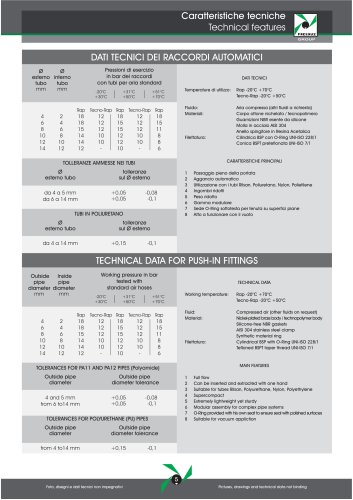
PRESSURE BOOSTER0 pages
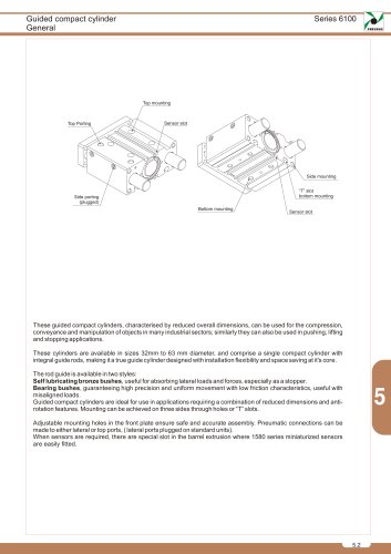
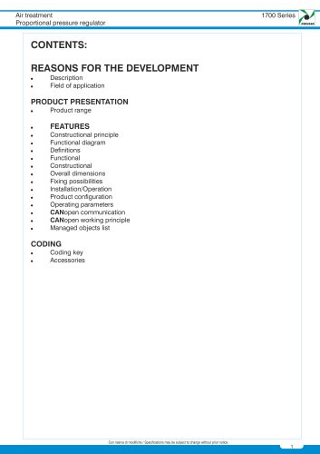
Air Service Units
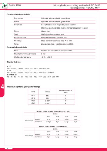
nnnnPressure booster
nnnnSeries 1700
nnnnPMEUMAX
nnnnGENERAL
nnnnIt is not unusual that, during some applications the thrust generated by a pneumatic cylinder is not sufficient
nnnnfor the specific purpose it has been designed for.
nnnnIn order to get over the problem, the working pressure may be increased to a maximum line pressure which
nnnnnormally is 6 - 7 bar; alternatively the problem is solved by an higher bore cylinder that suits the machine.
nnnnThree size pressure boosters, with pressure ratio of 1 - 2, have been designed to avoid these problems. This
nnnndevice is utilizing the compressed air of the circuit where it is installed.
nnnnCHAMBER 2 IN CHAMBER 3
nnnn--\-------------9
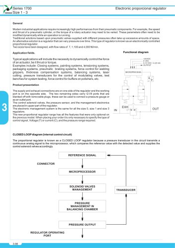
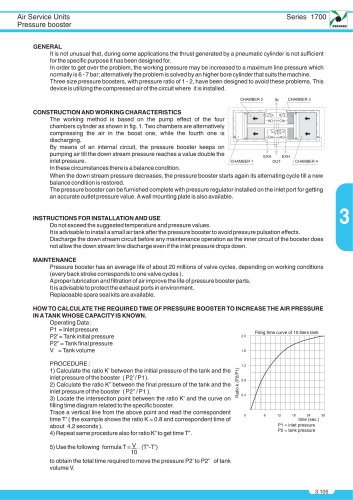
nnnnCONSTRUCTION AND WORKING CHARACTERISTICS
nnnnThe working method is based on the pump effect of the four
nnnnchambers cylinder as shown in fig. 1. Two chambers are alternatively
nnnncompressing the air in the boost one, while the fourth one is
nnnndischarging.
nnnnBy means of an internal circuit, the pressure booster keeps on
nnnnpumping air till the down stream pressure reaches a value double the
nnnninlet pressure.
nnnnIn these circumstances there is a balance condition.
nnnnWhen the down stream pressure decreases, the pressure booster starts again its alternating cycle till a new
nnnnbalance condition is restored.
nnnnThe pressure booster can be furnished complete with pressure regulator installed on the inlet port for getting
nnnnan accurate outlet pressure value. A wall mounting plate is also available.
nnnnINSTRUCTIONS FOR INSTALLATION AND USE
nnnnDo not exceed the suggested temperature and pressure values.
nnnnIt is advisable to install a small air tank after the pressure booster to avoid pressure pulsation effects.
nnnnDischarge the down stream circuit before any maintenance operation as the inner circuit of the booster does
nnnnnot allow the down stream line discharge even if the inlet pressure drops down.
nnnnMAINTENANCE
nnnnPressure booster has an average life of about 20 millions of valve cycles, depending on working conditions
nnnn(every back stroke corresponds to one valve cycles ).
nnnnA proper lubrication and filtration of air improve the life of pressure booster parts.
nnnnIt is advisable to protect the exhaust ports in environment.
nnnnReplaceable spare seal kits are available.
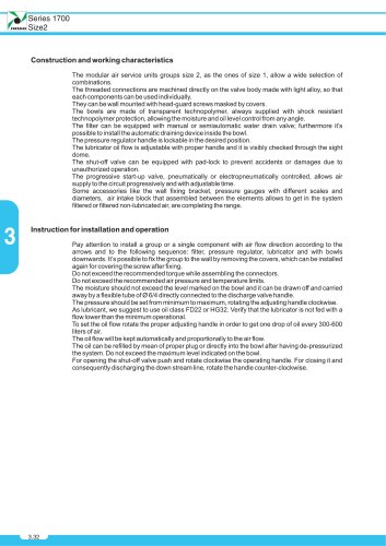
nnnnFiling time curve of 10 liters tank
nnnnHOW TO CALCULATE THE REQUIRED TIME OF PRESSURE BOOSTER TO INCREASE THE AIR PRESSURE
nnnnIN ATANKWHOSE CAPACITY IS KNOWN.
nnnnOperating Data :
nnnnP1 = Inlet pressure
nnnnP2'=Tank initial pressure
nnnnP2" = Tank final pressure
nnnnV = Tank volume
nnnnPROCEDURE:
nnnn1 ) Calculate the ratio K' between the initial pressure of the tank and the
nnnninlet pressure of the booster ( P27 P1 ).
nnnn2) Calculate the ratio K" between the final pressure of the tank and the
nnnninlet pressure of the booster (P2"/P1 ).
nnnn3) Locate the intersection point between the ratio K' and the curve on
nnnnfilling time diagram related to the specific booster.
nnnnTrace a vertical line from the above point and read the correspondent
nnnntime T' ( the example shows the ratio K = 0.8 and correspondent time of
nnnnabout 4.2seconds).
nnnn4) Repeat same procedure also for ratio K" to get time T".
nnnn5) Use the following formula T=Y.. (T"-T)
nnnnP1 :
nnnnP2:
nnnn24 30
nnnntime (sec.)
nnnninlet pressure
nnnntank pressure
nnnnto obtain the total time required to move the pressure P2' to P2" of tank
nnnnvolume V.
"