عضویت
عضویت  ورود اعضا
 راهنمای خرید


Diaphragm Valves 3" to 6"0 pages
DVIS REV A ECR 406S 01/04/2001 06U9.DOC >
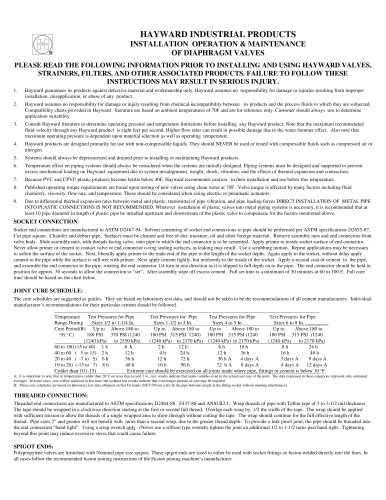
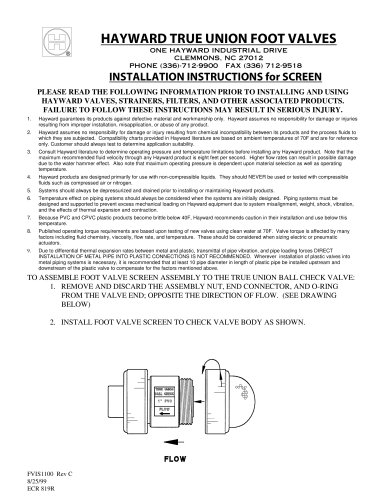
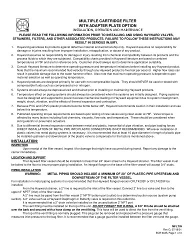
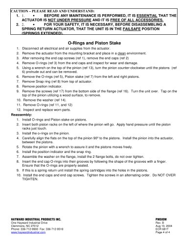
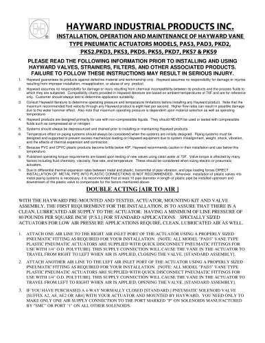
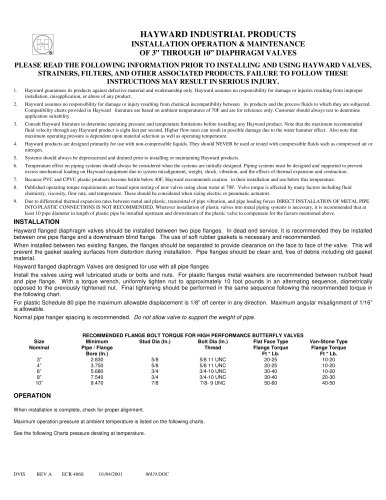
nnHAYWARD INDUSTRIAL PRODUCTS nnINSTALLATION OPERATION & MAINTENANCE OF 3 THROUGH 10Ԕ DIAPHRAGM VALVES
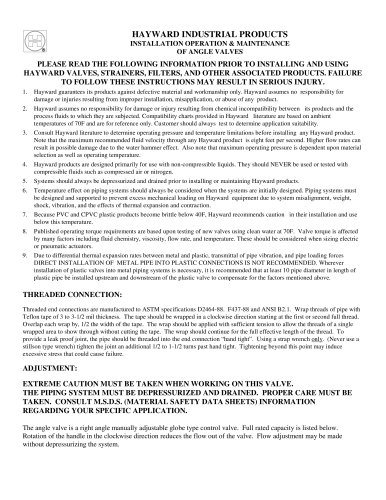
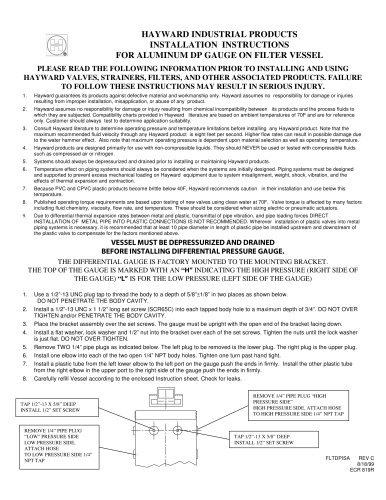
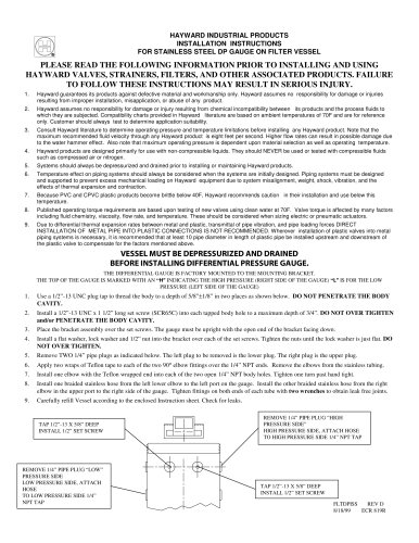
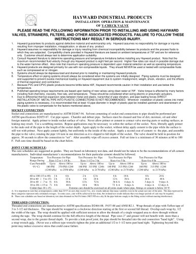
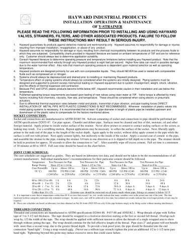
nnPLEASE READ THE FOLLOWING INFORMATION PRIOR TO INSTALLING AND USING HAYWARD VALVES, STRAINERS, FILTERS, AND OTHER ASSOCIATED PRODUCTS. FAILURE TO FOLLOW THESE INSTRUCTIONS MAY RESULT IN SERIOUS INJURY.
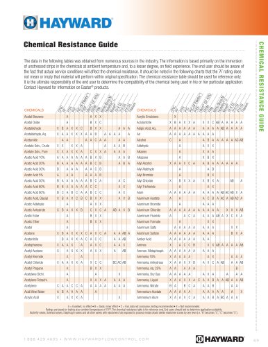
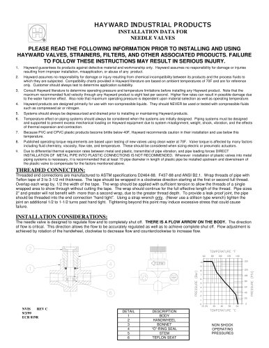
1. Hayward guarantees its products against defective material and workmanship only. Hayward assumes no responsibility for damage or injuries resulting from improper installation, misapplication, or abuse of any product. 2. Hayward assumes no responsibility for damage or injury resulting from chemical incompatibility between its products and the process fluids to which they are subjected. Compatibility charts provided in Hayward literature are based on ambient temperatures of 70F and are for reference only. Customer should always test to determine application suitability. 3. Consult Hayward literature to determine operating pressure and temperature limitations before installing any Hayward product. Note that the maximum recommended fluid velocity through any Hayward product is eight feet per second. Higher flow rates can result in possible damage due to the water hammer effect. Also note that maximum operating pressure is dependent upon material selection as well as operating temperature. 4. Hayward products are designed primarily for use with non-compressible liquids. They should NEVER be used or tested with compressible fluids such as compressed air or nitrogen. 5. Systems should always be depressurized and drained prior to installing or maintaining Hayward products. 6. Temperature effect on piping systems should always be considered when the systems are initially designed. Piping systems must be designed and supported to prevent excess mechanical loading on Hayward equipment due to system misalignment, weight, shock, vibration, and the effects of thermal expansion and contraction. 7. Because PVC and CPVC plastic products become brittle below 40F, Hayward recommends caution in their installation and use below this temperature. 8. Published operating torque requirements are based upon testing of new valves using clean water at 70F. Valve torque is affected by many factors including fluid chemistry, viscosity, flow rate, and temperature. These should be considered when sizing electric or pneumatic actuators. 9. Due to differential thermal expansion rates between metal and plastic, transmittal of pipe vibration, and pipe loading forces DIRECT INSTALLATION OF METAL PIPE INTO PLASTIC CONNECTIONS IS NOT RECOMMENDED. Wherever installation of plastic valves into metal piping systems is necessary, it is recommended that at least 10 pipe diameter in length of plastic pipe be installed upstream and downstream of the plastic valve to compensate for the factors mentioned above. >
nnINSTALLATION
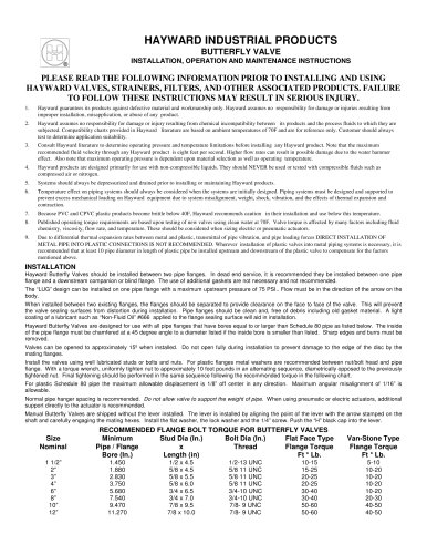
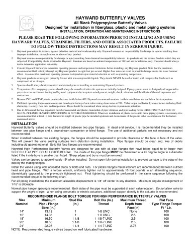
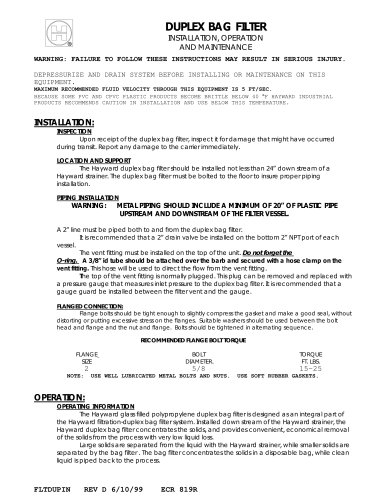
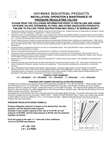
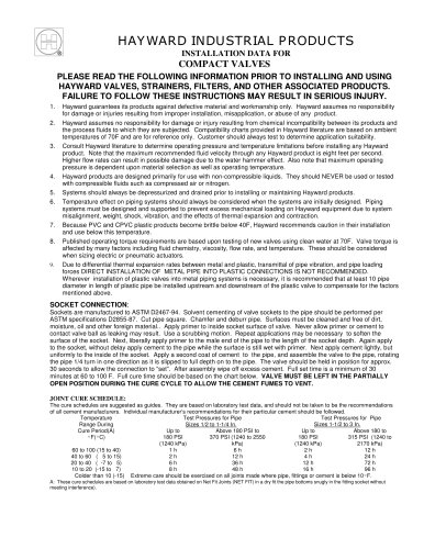
nnHayward flanged diaphragm valves should be installed between two pipe flanges. In dead end service, it is recommended they be installed between one pipe flange and a downstream blind flange. The use of soft rubber gaskets is necessary and recommended. When installed between two existing flanges, the flanges should be separated to provide clearance on the face to face of the valve. This will prevent the gasket sealing surfaces from distortion during installation. Pipe flanges should be clean and, free of debris including old gasket material. Hayward flanged diaphragm Valves are designed for use with all pipe flanges Install the valves using well lubricated studs or bolts and nuts. For plastic flanges metal washers are recommended between nut/bolt head and pipe flange. With a torque wrench, uniformly tighten nut to approximately 10 foot pounds in an alternating sequence, diametrically opposed to the previously tightened nut. Final tightening should be performed in the same sequence following the recommended torque in the following chart. For plastic Schedule 80 pipe the maximum allowable displacement is 1/8 off center in any direction. Maximum angular misalignment of 1/16Ԕ is allowable. Normal pipe hanger spacing is recommended. Do not allow valve to support the weight of pipe .RECOMMENDED FLANGE BOLT TORQUE FOR HIGH PERFORMANCE BUTTERFLY VALVES Size Nominal Minimum Pipe / Flange Bore (In.) Stud Dia (In.) Bolt Dia (In.) Thread Flat Face Type Flange Torque Ft * Lb. Van-Stone Type Flange Torque Ft * Lb. 3 2.830 5/8 5/8 11 UNC 20-25 10-20 4Ԕ 3.750 5/8 5/8 11 UNC 20-25 10-20 6 5.680 3/4 3/4-10 UNC 30-40 10-20 8Ԕ 7.540 3/4 3/4-10 UNC 30-40 20-30 10 9.470 7/8 7/8- 9 UNC 50-60 40-50 >
nnOPERATION
When installation is complete, check for proper alignment. Maximum operation pressure at ambient temperature is listed on the following charts. See the following Charts pressure derating at temperature. >
"