عضویت
عضویت  ورود اعضا
 راهنمای خرید


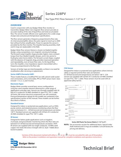
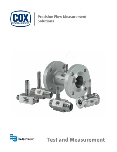
Recordall Turbo 450 Fire Hydrant Meter Size 3"0 pages
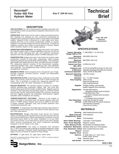
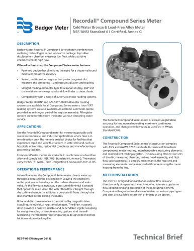
Recordall®
Turbo 450 Fire
Hydrant Meter
Technical
Brief
Size 3" (DN 80 mm)
DESCRIPTION
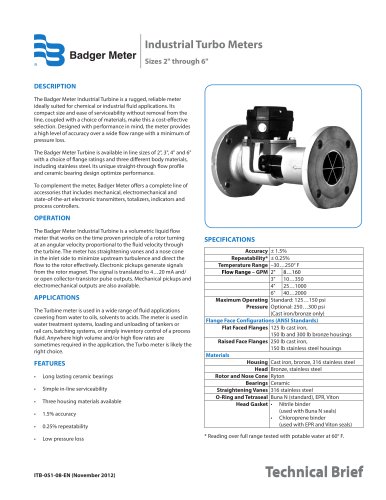
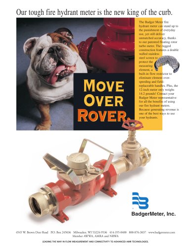
APPLICATIONS: For use in measurement of potable cold water from
a fire hydrant or other non-permanent installation where flow is in one
direction only.
OPERATION: Water flows into the meter's measuring element where
flow readings are obtained by rotor revolutions transmitted by
magnetic drive coupling through the meter's cover plate to the sealed
register. Magnetic drive is achieved by a right angle worm drive,
coupling the rotor to the vertical transmission spindle. A ceramic
magnet on the spindle rotates around the vertical axis. Through the
magnetic coupling, rotor rotation is transmitted to a follower magnet
which transmits rotation to the register gearing.
OPERATING PERFORMANCE: The Badger Recordall Turbo Series
fire hydrant meters meet or exceed registration accuracy for the low
flow rate, normal operating flow rate, and maximum continuous
operation flow rate as specifically stated in AWWA Standard C701.
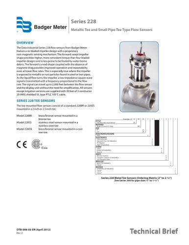
CONSTRUCTION: Badger Recordall Turbo Series fire hydrant meter
construction consists of three basic components: meter housing,
measuring element and permanently sealed register. The housing is
light-weight heat treated aluminum alloy, compact and easy to handle.
The measuring element consists of the transmission coupling,
measuring element insert, rotor, straightening vane, and calibration
vane assembly. The straightening vanes minimize swirl from piping
arrangements upstream.
MAGNETIC DRIVE: Direct magnetic drive, through the use of highstrength magnets, provides positive, reliable and dependable
register coupling.
RESTRICTION PLATE: A permanent orifice, positioned in the outlet
side of the housing, limits the maximum flow of water through the
meter. This is provided to protect the measuring element from
overspeeding when the meter discharges to atmosphere.
SEALED REGISTER: The standard register consists of a straightreading odometer-type totalization display, 360° test circle with
center sweep hand and flow finder to detect leaks. Register gearing
consists of self-lubricating thermoplastic gears to minimize friction
and provide long life. Permanently sealed; dirt, moisture, tampering
and lens fogging problems are eliminated. Multi-position register
simplifies meter installation and reading.
TAMPER-RESISTANT FEATURES: Removal of the register to
obtain free water is prevented when the tamper detection seal wire
screw or TORX® tamper resistant seal screw is added to the meter.
A tamper resistant calibration plug seal provides protection from
unauthorized personnel use.
STRAINER: A compression fit double layer stainless steel strainer is
installed in the inlet housing tube. The strainer insures optimum longterm field performance.
MAINTENANCE: Badger Recordall Turbo Series fire hydrant
meters are designed and manufactured to provide long-term service
with minimal maintenance. When maintenance is required, it can be
performed easily either at the meter installation or at any other
convenient location. As an alternative to repair by the utility, Badger
offers various maintenance and meter component exchange
programs to fit the needs of the utility.
HOSE COUPLINGS: The meter is available with standard
(2½"-7 NST) fire hose swivel couplings as standard equipment unless
otherwise specified. Complete thread specifications (listed on back
page) must be furnished for special fire hose fittings.
OPTIONS: 2" gate valve, 2½" gate valve, check valve.
Recordall® is a registered trademark of Badger Meter, Inc. TORX® is a registered trademark
of Camcar, Division of Textron, Inc.
BadgerMeter, Inc.
®
Turbo 450 with
Optional
Connections
SPECIFICATIONS
Typical Operating
Range (100%±1.5%)
Maximum
Continuous Flow
Maximum
Intermittant Flow
Typical Low Flow
(Min. 95%)
Pressure Loss
at Maximum
Continuous Operation
Maximum Operating
Pressure
Standard
Hose Coupling
Register
Registration
Flow Restriction
(Orifice)
5 - 660 GPM (1.1 to 150 m3/h)
450 GPM (102 m3/h)
660 GPM (150 m3/h)
4 GPM (0.9 m3/h)
37 PSI @ 450 GPM (2.55 bar @ 102 m3/h)
(standard couplings with orifice and screen)
Note: 23 PSI @ 350 GPM
150 PSI (10 bar)
2½" - 7½ NST threads
(78P-3.4mm)
(National standard fire
hose coupling thread)
Straight reading, permanently
sealed magnetic drive standard.
100,000,000 Gallons
100 gallons/sweep hand revolution.
10,000,000 Cubic Feet
10 cubic ft./sweep hand revolution.
1,000,000 m3
1 m3/sweep hand revolution.
Limits flow through the meter
to 660 GPM at 85 PSI system pressure
with standard couplings.
(150 m3/h at 5.9 bar)
MATERIALS
Housing
Nose Cone and
Straightening Vanes
Rotor
Rotor Radial Bearings
Rotor Thrust Bearings
Rotor Bearing Pivots
Calibration Mechanism
Flow Restriction Orifice
Magnet
Register Cover
Options
Trim
Inlet Screen
Heat treated aluminum alloy
Thermoplastic
Thermoplastic
Lubricated Thermoplastic
Sapphire Jewels
Passivated 316 Stainless Steel
Stainless Steel and Thermoplastic
Heat Treated Aluminum Alloy
Ceramic
Bronze
2" Gate Valve, 2½" Gate Valve,
Check Valve, Bronze
Stainless Steel
Stainless Steel with Elastomer
RTS-T-3FH
6-07