عضویت
عضویت  ورود اعضا
 راهنمای خرید


Glass Mid-Range 0737-0101-990 pages
DATA SHEET
`
Operating Specifications
Description
The 0737-0101-99 Sensor has been used successfully in
applications that demand ultra high accuracy, excellent null
repeatability, mid-range angle measurement and a linear
output. Long term stability over its angle and temperature
range is a distinctive characteristic of this sensor. The
hermetic glass to metal construction and platinum electrodes
guarantee a long operating life and stable operating
characteristics.
Angle Range
Resolution
Null Repeat
10
<1.0 arc second
< 2.0 arc-seconds
Applications Include
»
»
»
»
»
Geophysical Monitoring
Construction Laser Instruments and Transits
Aircraft Avionics
Machine Tool Leveling
Medical Positioning and Monitoring
1
Measured left to right electrode, Impedance of the electrode
may be changed to limit null current.
2
Viscosity of the electrolyte may be modified to meet
individual requirements for time constant or vibration.
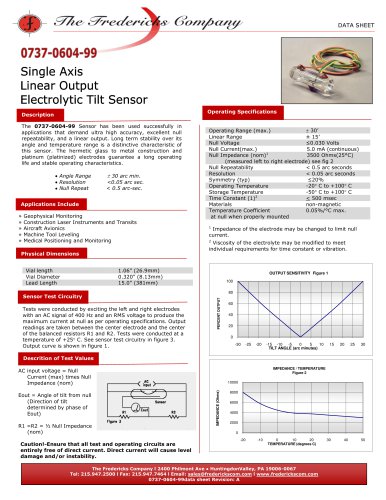
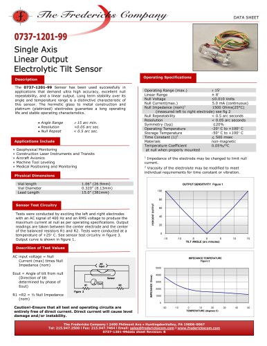
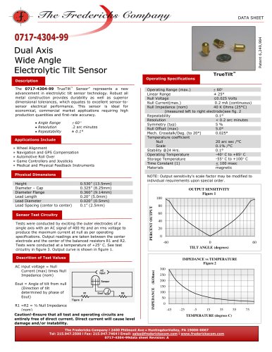
OUTPUT SENSITIVITY
Figure 1
Physical Dimensions
1.13” max (28.70mm)
0.320”max (8.13mm)
15.0” max (381mm)
custom lead length available
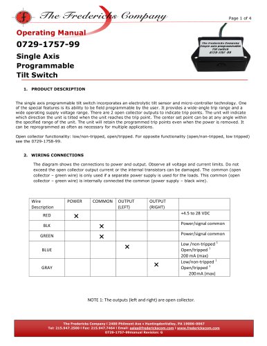
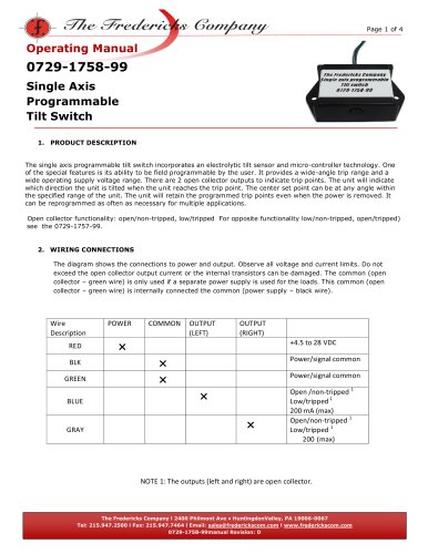
Sensor Test Circuitry
Tests were conducted by exciting the left and right electrodes
with an AC signal of 400 Hz and an RMS voltage to produce the
maximum current at null as per operating specifications. Output
readings are taken between the center electrode and the center
of the balanced resistors R1 and R2. Tests were conducted at a
temperature of +25 C. See sensor test circuitry in figure 3.
Output curve is shown in figure 1.
100
80
PERCENT OUTPUT
Vial length
Vial Diameter
Lead Length
10
± 5°
≤0.030 Volts
5.0 mA (continuous)
3600Ω@25°C
< 2.0 arc seconds
< 1.0 arc seconds
5% max.
-40 C to +80 C
-50 C to +100 C
< 500 ms
non-magnetic
0.02%/°C max.
Operating Range (max.)
Linear Range
Null Voltage
Null Current(max.)
Null Impedance (nom)1
Null Repeatability
Resolution
Symmetry @ ½ scale
Operating Temperature
Storage Temperature
Time Constant 2
Materials
Temperature Coefficient at Null
60
40
20
0
-10
-8
-6
-4
-2
0
2
4
6
8
10
TILT ANGLE (degrees)
Descrition of Test Values
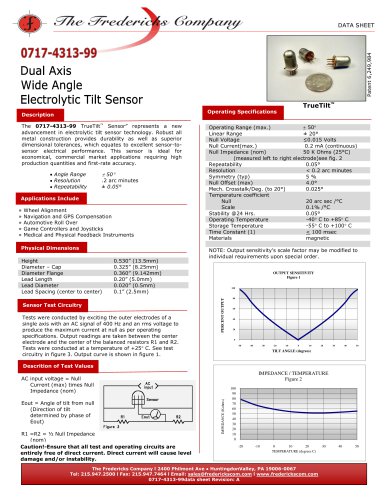
IMPEDANCE vs. TEMPERATURE
Figure 2
AC input voltage = Null
Current (max) times Null
Impedance (nom)
20
18
16
R1 =R2 = ½ Null Impedance
(nom)
14
IMPEDANCE (kΩ)
Eout = Angle of tilt from null
(Direction of tilt
determined by phase of
Eout)
12
10
8
6
4
2
0
Caution!-Ensure that all test and operating circuits are
entirely free of direct current. Direct current will cause level
damage and/or instability.
-40
-30
-20
-10
0
10
20
30
TEMPERATURE (°C)
The Fredericks Company l 2400 Philmont Ave ● HuntingdonValley, PA 19006-0067
Tel: 215.947.2500 l Fax: 215.947.7464 l Email: sales@frederickscom.com l www.frederickscom.com
0737-0101-99data sheet Revision: A
40
50
60
70
80
"