عضویت
عضویت  ورود اعضا
 راهنمای خرید


TrueTILT? Wide Range 0717-4304-990 pages
DATA SHEET
Patent 6,249,984
`
The 0717-4304-99 TrueTilt Sensor” represents a new
advancement in electrolytic tilt sensor technology. Robust all
metal construction provides durability as well as superior
dimensional tolerances, which equates to excellent sensor-tosensor electrical performance. This sensor is ideal for
economical, commercial market applications requiring high
production quantities and first-rate accuracy.
Angle Range
Resolution
Repeatability
60
.2 arc minutes
± 0.1°
Applications Include
Wheel Alignment
Navigation and GPS Compensation
Automotive Roll Over
Game Controllers and Joysticks
Medical and Physical Feedback Instruments
Physical Dimensions
Height
Diameter – Cap
Diameter Flange
Lead Length
Lead Diameter
Lead Spacing (center to center)
0.530” (13.5mm)
0.325” (8.25mm)
0.360” (9.14mm)
0.20” (5.0mm)
0.020” (0.5mm)
0.1” (2.5mm)
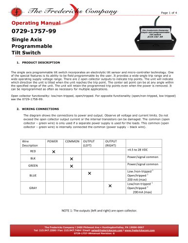
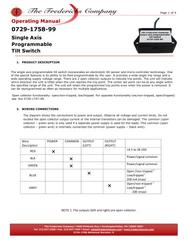
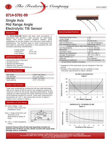
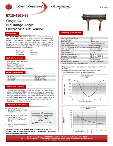
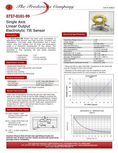
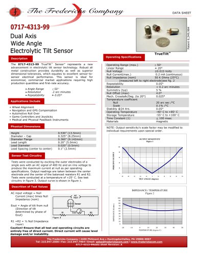
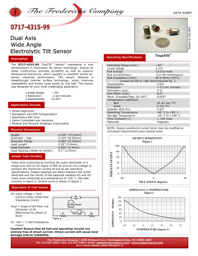
Sensor Test Circuitry
Tests were conducted by exciting the outer electrodes of a
single axis with an AC signal of 400 Hz and an rms voltage to
produce the maximum current at null as per operating
specifications. Output readings are taken between the center
electrode and the center of the balanced resistors R1 and R2.
Tests were conducted at a temperature of +25 C. See test
circuitry in figure 3. Output curve is shown in figure 1.
60
Operating Range (max.)
Linear Range
± 25°
Null Voltage
≤0.025 Volts
Null Current(max.)
0.2 mA (continuous)
Null Impedance (nom)
40 K Ohms (25°C)
(measured left to right electrode)see fig. 2
Repeatability
0.1°
Resolution
< 0.2 arc minutes
Symmetry (typ)
5%
Null Offset (max)
5.0°
Mech. Crosstalk/Deg. (to 20°)
0.025°
Temperature coefficient
Null
20 arc sec /°C
Scale
0.1% /°C
Stability @24 Hrs.
0.1°
-40 C to +85 C
Operating Temperature
-55 C to +100 C
Storage Temperature
Time Constant (1)
< 100 msec
Materials
magnetic
NOTE: Output sensitivity’s scale factor may be modified to
individual requirements upon special order.
OUTPUT SENSITIVITY
Figure 1
100
PERCENT OUTPUT
Description
»
»
»
»
»
TrueTilt
Operating Specifications
80
60
40
20
0
-60
Descrition of Test Values
Eout = Angle of tilt from null
(Direction of tilt
determined by phase of
Eout)
R1 =R2 = ½ Null Impedance
(nom)
Caution!-Ensure that all test and operating circuits are
entirely free of direct current. Direct current will cause level
damage and/or instability.
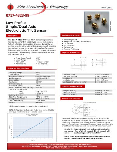
60
IMPEDANCE vs TEMPERATURE
Figure 2
IMPEDANCE (KOhms)
AC input voltage = Null
Current (max) times Null
Impedance (nom)
0
TILT ANGLE (degrees)
300
250
200
150
100
50
0
-45
-25
-5
15
35
TEMPERATURE (degrees C)
The Fredericks Company l 2400 Philmont Ave ● HuntingdonValley, PA 19006-0067
Tel: 215.947.2500 l Fax: 215.947.7464 l Email: sales@frederickscom.com l www.frederickscom.com
0717-4304-99data sheet Revision: A
55
75
"