عضویت
عضویت  ورود اعضا
 راهنمای خرید


Digital step attenuators PE43040 pages

Product Specification
PE4304
75 Ω RF Digital Attenuator
6-bit, 31.5 dB, DC – 2.0 GHz
Product Description
The PE4304 is a 75-ohm high-linearity, 6-bit RF Digital Step
Attenuator (DSA) covering a 31.5 dB attenuation range in 0.5
dB steps. The PE4304 provides both a parallel (latched or
direct mode) and serial CMOS control interface, operates on a
single 3-volt supply and maintains high attenuation accuracy
over frequency and temperature. It also has a unique control
interface that allows the user to select an initial attenuation
state at power-up. The PE4304 exhibits very low insertion loss
and low power consumption. This functionality is delivered in a
4x4 mm QFN footprint.
The PE4304 is manufactured on Peregrine’s UltraCMOS™
process, a patented variation of silicon-on-insulator (SOI)
technology on a sapphire substrate, offering the performance
of GaAs with the economy and integration of conventional
CMOS.
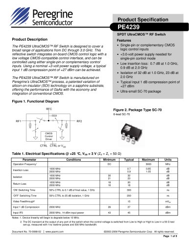
Figure 1. Functional Schematic Diagram
Features
• 75 Ω impedance
• Attenuation: 0.5 dB steps to 31.5 dB
• Low distortion for CATV and multi-carrier
applications
• Flexible parallel and serial programming
interfaces
• Unique power-up state selection
• Positive CMOS control logic
• High attenuation accuracy and linearity
over temperature and frequency
• Very low power consumption
• Single-supply operation
• Packaged in a 20 lead 4x4 mm QFN
Figure 2. Package Type
4x4 mm 20-Lead QFN
Switched Attenuator Array
RF Input
RF Output
Parallel Control
6
Serial Control
3
Power-Up Control
2
Control Logic Interface
Table 1. Electrical Specifications @ +25 °C, VDD = 3.0 V, Zo = 75 Ω
Parameter
Test Conditions
Frequency
Operation Frequency
Insertion Loss
Notes: 1.
2.
3.
4.
Units
2000
MHz
50% control to 0.5 dB
of final value
1.4
1.8
dB
DC ≤ 1.2 GHz
-
-
±(0.15 + 4% of attenuation
setting)
dB
30
34
-
dBm
1 MHz ≤ 1.2 GHz
-
52
-
dBm
DC ≤ 1.2 GHz
Two-tone inputs up to
+18 dBm
-
1 MHz ≤ 1.2 GHz
Any Bit or Bit
Combination
Return Loss
Switching Speed
Maximum
DC ≤ 1.2 GHz
1 dB Compression3,4
Input IP31,2,4
Typical
DC
2
Attenuation Accuracy
Minimum
10
13
-
dB
-
-
1
µs
Device Linearity will begin to degrade below 1Mhz
Max input rating in Table 3 & Figures on Pages 4 to 6 for data across frequency.
Note Absolute Maximum in Table 3.
Measured in a 50 Ω system.
Document No. 70-0066-04 │ www.psemi.com
©2003-2006 Peregrine Semiconductor Corp. All rights reserved.
Page 1 of 11