عضویت
عضویت  ورود اعضا
 راهنمای خرید


M10 pages

Type: M1ARM
Asymmetrical Recycler - Selectable On or Off first
q
q
q
q
q
q
q
17.5mm DIN rail housing
Asymmetrical Recycling Off/On or On/Off (selectable)
Multi-voltage supply: 24 - 240V AC / DC
Selectable time ranges for “On” and “Off” periods (up to 60mins)
Separate adjustments for “On” and “Off” periods
1 x SPDT relay output 8A
LED indication of supply and output relay status
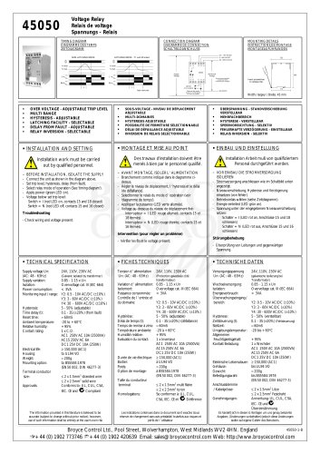
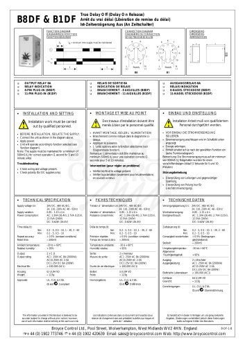
• FUNCTION DIAGRAM
Dims:
to DIN 43880
W. 17.5mm
Terminal Protection to IP20
• TECHNICAL SPECIFICATION
ton
t off
t on
Recycling - Off first (A1 & B1 linked)
t off
t off
t on
t off
Supply voltage U:
Supply variation:
Power
consumption:
24 - 240V AC / DC (AC: 48 - 63Hz)
75 - 110% of U
Functions:
Recycling - On first (A1 & B1 not linked)
Asymmetrical Recycling - Off first*
Asymmetrical Recycling - On first
(* selected when external link fitted)
t on
Time delay (ton/off) :
(selectable)
Repeat accuracy:
Reset time:
• INSTALLATION AND SETTING
Installation work must be carried
out by qualified personnel.
•
•
BEFORE INSTALLATION, ISOLATE THE SUPPLY.
0.5 - 15, 2 - 60 seconds
0.25 - 8, 2 - 60 minutes
± 0.5% @ constant conditions
≈ 100mS
Ambient temp:
Relative humidity:
-20 to +60°C
+95%
Output:
Output rating:
SPDT relay
AC1
250V 8A (2000VA)
AC15
250V 5A (no), 3A (nc)
DC1
25V 8A (200W)
Housing:
Weight:
Mounting option:
Orange flame retardant UL94 VO
≈ 68g
On to 35mm symmetric DIN rail to
BS5584:1978
(EN50 002, DIN 46277-3)
Or direct surface mounting via 2 x
M3.5 or 4BA screws using the black
clips provided on the rear of the unit
Connect the unit as shown in the diagram below. (Fit external link if required).
To set the unit:
•
•
Select the “time range” DIP switches for the “on period” and “off period” (see below).
Set the “delay” adjustment as required. (Note the scale is marked as a % of the selected time
range).
A
B
A
B
A
B
A
B
On
Off
0.5 - 15s
2 - 60s
0.25 - 8m
2 - 60m
Switch positions shown above for the "Off period".
The same positions are used for the "On period"
(top two switches).
•
•
≈ 3VA @ 240V AC
0.8W @ 24V DC
Apply power (green LED on). The unit will operate according to the function selected.
During the “on period”, the relay will be energised (red LED on, contacts 15/18 closed).
During the “off period”, the relay will be de-energised (red LED off, contacts 15/16 closed).
Terminal
conductor size:
≤ 2 x 2.5mm2 solid or stranded
Approvals:
Conforms to IEC. CE and
Compliant.
Troubleshooting.
•
If the unit fails to operate, check the wiring is correct and the supply voltage is present and
within the operating limits specified.
• CONNECTION DIAGRAM
-ve
Supply
+ve
* link
•
MOUNTING DETAILS
89 (excl. clips)
A1 B1
15
* Fit external link
(A1 to B1) for "Off first"
recycling
45
Insert screwdriver
to release clips
16 18
49 59
A2
Withdraw clips
fully when
surface mounting
93 (+/- 1mm)
M1ARM-1-A
Broyce Control Ltd., Pool Street, Wolverhampton, West Midlands WV2 4HN. England
Telephone: +44 (0) 1902 773746 Facsimile: +44 (0) 1902 420639 Email: sales@broycecontrol.com Web: http://www.broycecontrol.com
The information provided in this literature is believed to be accurate (subject to change without prior notice); however, use of such information shall be entirely at the user’s own risk.