عضویت
عضویت  ورود اعضا
 راهنمای خرید


Safety Relay SRLC0 pages

Emergency Stop Safety Relay SRLC
User Information
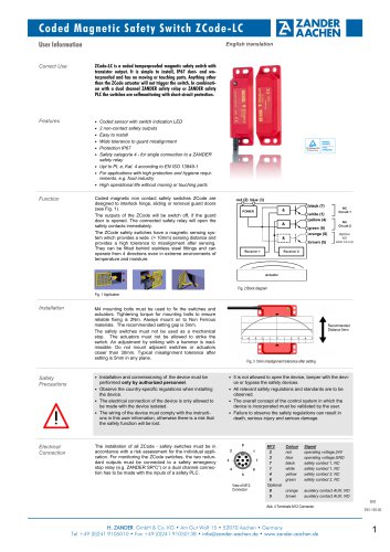
Correct Use
English translation
SRLC is low-cost emergency stop safety relay with which machines and systems can be safely switched off by disconnecting
the power supply.
Applications for the SRLC include single or dual-channel emergency stop circuits and guard monitoring on machines and systems.
Features
• 2 safe, redundant relay outputs
(not for plug-in terminals)
• Connection of:
•
•
•
•
Function
Installation
- Emergency stop buttons
- Safety switches
- Non-contact safety switches
Single and dual-channel operation possible
Feedback loop for monitoring downstream contactors or
expansion modules
Cyclical monitoring of the output contacts
Indication of the switching state via LED
The emergency stop safety switching device SRLC is
designed for safe isolation of safety circuits according to
EN 60204-1 and can be used up to safety category 3, PL d
according to EN ISO 13849-1.
The internal logical system closes the safety contacts when
the start button is pressed.
If the safety switch is opened, the positively driven safety
contacts are opened and safely switch the machine off. It is
ensured that a single fault does not lead to a loss of the
safety function and that every internal fault is detected by
cyclical self-monitoring no later than when the system is
switched off and switched on again. Only a fault in the
safety switch itself is not detected. This must be checked
regularly as part of a maintenance plan.
• 2 start behaviors possible:
- Manual start
- Automatic start
• Short circuit and earth fault monitoring
• Up to PL d, SILCL 2, category 3
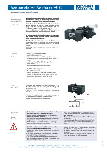
Fig. 1 Block diagram SRLC
As per EN 60204-1, the device is intended for installation in
control cabinets with a minimum degree of protection of
IP54. It is mounted on a 35 mm DIN rail according to DIN
EN 60715 TH35.
Fig. 2 Installation / removal
Safety
Precautions
• Installation and commissioning of the device must be
•
•
•
•
Electrical
Connection
performed only by authorized personnel.
Observe the country-specific regulations when installing
the device.
The electrical connection of the device is only allowed to
be made with the device isolated.
The wiring of the device must comply with the instructions in this user information, otherwise there is a risk
that the safety function will be lost.
It is not allowed to open the device, tamper with the
device or bypass the safety devices.
• When the 24 V version is used, a control transformer
•
•
•
•
according to EN 61558-2-6 or a power supply unit with
electrical isolation from the mains must be connected.
External fusing of the contacts (4 A slow-blow or 6 A
quick-action or 10 A gG) must be provided.
A maximum length of the control lines of 1000 meters
with a line cross section of 0.75 mm2 must not be exceeded.
The line cross section must not exceed 2.5 mm2.
If the device does not function after commissioning, it
must be returned to the manufacturer unopened. Opening the device will void the warranty.
• All relevant safety regulations and standards are to be
observed.
• The overall concept of the control system in which the
device is incorporated must be validated by the user.
• Failure to observe the safety regulations can result in
death, serious injury and serious damage.
• Note down the version of the product (see label “Ver: x”)
and check it prior to every commissioning of a new device. If the version has changed, the overall concept of
the control system in which the device is incorporated
must be validated again by the user.
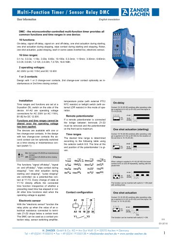
A1:
A2 :
S11:
S21:
13-14:
23-24:
Power supply
Power supply
DC 24 V control voltage
Control line
Safety contact 1
Safety contact 2
Fig. 3 Connections
E11
Ver. B
E61-143-00
H. ZANDER GmbH & Co. KG • Am Gut Wolf 15 • 52070 Aachen • Germany
Tel +49 (0)241 9105010 • Fax +49 (0)241 91050138 • info@zander-aachen.de • www.zander-aachen.de
1
"