عضویت
عضویت  ورود اعضا
 راهنمای خرید


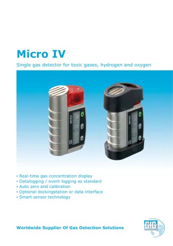
MICRO IV Dockingstation DS2200 pages
GfG Gesellschaft für Gerätebau mbH
Klönnestraße 99 – D-44143 Dortmund
Phone +49-(0)231-56400 0
Fax
+49-(0)231-516313
E-Mail info@gfg.biz
Internet www.gfg.biz
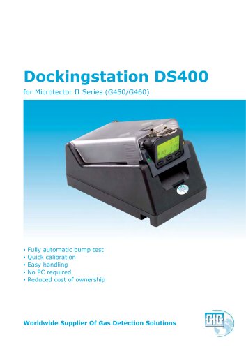
MICRO IV Dockingstation DS220
Shortform Manual – Function Test
Application
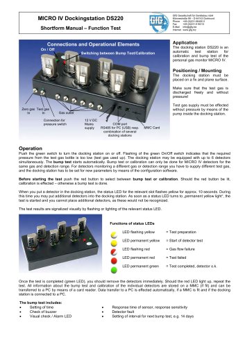
Connections and Operational Elements
On / Off
Switching between Bump Test/Calibration
The docking station DS220 is an
automatic
test
station
for
calibration and bump test of the
personal gas monitor MICRO IV.
Positioning / Mounting
The docking station must be
placed on a fix and plane surface.
Make sure that the test gas is
discharged freely and without
pressure!
Zero gas Test gas
In
In
Test gas supply must be effected
without pressure by means of the
pump inside the docking station.
Gas outlet
Connection for
pressure switch
12 V DC
Mains
supply
COM port
RS485 for PC (USB) resp.
combination of several
docking stations
MMC Card
Operation
Push the green switch to turn the docking station on or off. Flashing of the green On/Off switch indicates that the required
pressure from the test gas bottle is too low (test gas used up). The docking station may be equipped with up to 6 detectors
simultaneously. The bump test starts automatically. Bump test or calibration can only be done for MICRO IV detectors for the
same gas and detection range. For detectors monitoring a different gas or detection range you have to supply different test gas,
and the docking station has to be set for new parameters by means of the configuration software.
Before starting the test push the red button to select between bump test or calibration. Should the red button be lit,
calibration is effected – otherwise a bump test is done.
When you put a detector in the docking station, the status LED for the relevant slot flashes yellow for approx. 10 seconds. During
this time you may put additional detectors into the docking station. As soon as a status LED turns to „permanent yellow light“, the
test is started and you cannot place additional detectors, as these would not be recognized.
The test results are signalized visually by flashing or lighting of the relevant status LED.
Functions of status LEDs
LED flashing yellow
= Test preparation
LED permanent yellow
= Start of detector test
LED flashing red
= Gas flow failure
LED permanent red
= Test failed
LED permanent green
= Test completed, detector o.k.
Once the test is completed (green LED), you should remove the detectors immediately. Should the red LED light up, repeat the
test. All information about the bump test and calibration of the individual detectors are stored on a MMC (if fit) and can be
transferred to a PC by means of a card reader. Data transfer to a PC is effected automatically, if a MMC is fit and if the docking
station is connected to a PC.
The bump test includes:
Setting of time
Check of buzzer
Visual check / Alarm LED
Response time of sensor, response sensitivity
Detector fault
Setting of interval for next bump test, e.g. 14 days