عضویت
عضویت  ورود اعضا
 راهنمای خرید


MP: Weighing structure0 pages
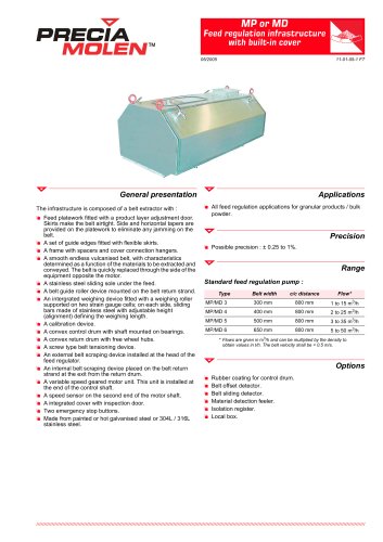
MP or MD
nnnnMOLEN™
nnnnFeed regulation infrastructure R^^-A
nnnnwith built-in cover fiHSP^
nnnn05/2005
nnnn11-01-05-1 FT
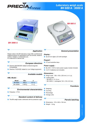
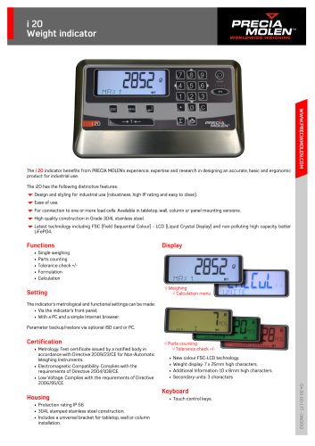
nnnnGeneral presentation
nnnnThe infrastructure is composed of a belt extractor with :
nnnn1 Feed platework fitted with a product layer adjustment door.
nnnnSkirts make the belt airtight. Side and horizontal tapers are
nnnnprovided on the platework to eliminate any jamming on the
nnnnbelt.
nnnn1 A set of guide edges fitted with flexible skirts.
nnnn1 A frame with spacers and cover connection hangers.
nnnn1 A smooth endless vulcanised belt, with characteristics
nnnndetermined as a function of the materials to be extracted and
nnnnconveyed. The belt is quickly replaced through the side of the
nnnnequipment opposite the motor.
nnnn1 A stainless steel sliding sole under the feed.
nnnn1 A belt guide roller device mounted on the belt return strand.
nnnn1 An intergrated weighing device fitted with a weighing roller
nnnnsupported on two strain gauge cells; on each side, sliding
nnnnbars made of stainless steel with adjustable height
nnnn(alignment) defining the weighing length.
nnnn1 A calibration device.
nnnn1 A convex control drum with shaft mounted on bearings.
nnnn1 A convex return drum with free wheel hubs.
nnnn1 A screw type belt tensioning device.
nnnn1 An external belt scraping device installed at the head of the
nnnnfeed regulator.
nnnn1 An internal belt scraping device placed on the belt return
nnnnstrand at the exit from the return drum.
nnnn1 A variable speed geared motorunit. This unit is installed at
nnnnthe end of the control shaft.
nnnn1 A speed sensor on the second end of the motor shaft.
nnnn1 A integrated cover with inspection door.
nnnn1 Two emergency stop buttons.
nnnn1 Made from painted or hot galvanised steel or 304L / 316L
nnnnstainless steel.
nnnnApplications
nnnnm All feed regulation applications for granular products / bulk
nnnnpowder.
nnnnPrecision
nnnn1 Possible precision : ± 0.25 to 1%.
nnnnRange
nnnnStandard feed regulation pump :
nnnnType Belt width c/c distance
nnnnFlow*
nnnnMP/MD 3
nnnn300 mm
nnnn800 mm
nnnn1 to 15 m3/h
nnnnMP/MD 4
nnnn400 mm
nnnn800 mm
nnnn2 to 25 m3/h
nnnnMP/MD 5
nnnn500 mm
nnnn800 mm
nnnn3 to 35 m3/h
nnnnMP/MD 6
nnnn650 mm
nnnn800 mm
nnnn5 to 50 m3/h
nnnn* Flows are given in m Ih and can be multiplied by the density to
nnnnobtain values in t/h. The belt velocity shall be < 0.5 m/s.
nnnnOptions
nnnnm Rubber coating for control drum.
nnnn1 Belt offset detector.
nnnn1 Belt sliding detector.
nnnn1 Material detection feeler.
nnnn1 Isolation register.
nnnn1 Local box.
nnnniiiiiiiiiiiiiiiiiiiiiiiiiiiiiiiiiiiiiiiiiiiiiiiiiiiiiiiiiiiiiiiiiiiiiiiiiiiiiiiiiiiiiiiiiiiiiiiiiiiiiiiiiiiiiiiiiiiiiiiiiiiiiiiiiiiiiiiiiiiiiiiiiiiiiiiiiiiiiiiiiiiiiiiiiiiiiiiiiiiiiiiiiiiiiiiiiiiiiiiiiiiiiiiiiiiiii
"