عضویت
عضویت  ورود اعضا
 راهنمای خرید


FM 120 pages

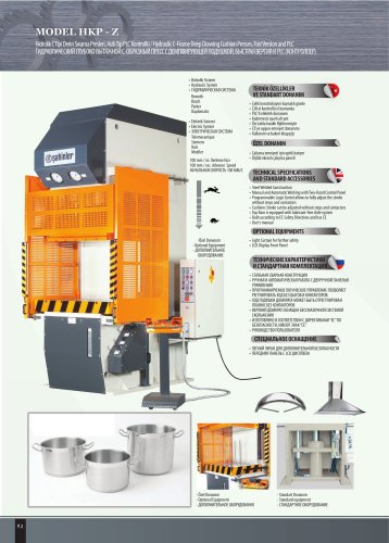
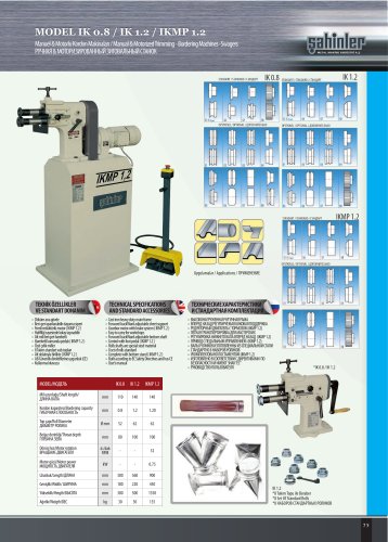
MODEL FM 12
Bombe Bükme Makinası / Flanging Machine
КРОМКОЗАГИБОЧНЫЙ СТАНОК
Kenar Bükme
Flanging
Сгиб краев
TEKNİK ÖZELLİKLER
VE STANDART DONANIM
TECHNICAL SPECIFICATIONS
AND STANDARD ACCESSORIES
Bu makina tanker ve kazan kapaklarının bombe sıvama radyus yapımı için
tasarlanmıştır. En önemli özellikleri şunlardır:
•t Alt ve üst yapı ayrı ayrı kaynaklı olarak imal edilmiştir. Kaynak gerilimleri
termal olarak alındıktan sonra çok sağlam bir şekilde montajı yapılmıştır.
•t Alt sıvama ve üst sıvama millerinin blokları gövdeye kızak sistemi ile
yataklanmıştır.
•t Motorlu alt sıvama topu grubu bilyalı rulmanlar ile donatılmış ve sıvama
esnasında parçanın altından destek yapmaktadır. Alt pozisyon ayarı için
hidrolik bir pistonla hareket etmektedir.
•t Yapılacak radyusa göre özel şekillendirilmiş üst sıvama topları yüksek
mukavemetli çelik malzemeden mamul olup sertleştirilmiştir. Bu top radyal
pistonlu pompa ile tahrik edimiş olup kademesiz hız ayarı ile donatılmıştır.
•t Yapılacak radyusa göre özel şekillendirilmiş alt sıvama topları yüksek
mukavemetli çelik malzemeden mamul olup, induksiyon ile sertleştirilmiştir
Hidrolik piston grubu ile malzemeyi alttan yukarı doğru iterek şekillendirme
görevini yapar.
•t Alt destek dayamaları üst sıvama topunun altına yerleştirilmiş olup,
tankerin alt kısmını sıvama esnasında destekler. Yükseklikleri hidrolik olarak
ayarlanabilir.
•t Hidrolik malzemeler dünyaca tanınmış markalardan kullanılmıştır.
•t Hidrolik sistem motor pompa grubu, yağ tankı, kirlilik uyarılı filtre,
seviye göstergesi, termostat, soğutma sistemi ve gerekli valf grubundan
oluşmaktadır.
•t Elektrik sistem Telemecanique veya Siemens ürünlerinden oluşmaktadır.
•t Ana kart transformatörlü, güç ve koruma komponentlerinden oluşmaktadır.
•t Kontrol paneli çalıştırma anahtarlı, acil durum uyarı lambalı, hareket kolu ve
makinanın komple manuel ve otomatik kontrolünü sağlayan butonlar.
84
This machine has been studied for the execution of the edges of tank bottoms
and it essentially consists of:
•t Electro-welded frame, thermally stress relived. The structural assembly of the
machine assures high sturdiness and stability during flanging.
•t Motorized lower bottom-holder carriage runs on slides and translates by
means of worm screw. The slides are fixed on the base frame.
•t The hydraulic cylinder which allows bottom height adjustment is fixed on the
bottom-holder carriage.
•t The standard machine can flange bottom to with center-hole, on request is
possible supply machine for bottoms without center-hole.
•t The shaping roll, built in high resistance steel and induction hardened, is
properly shaped according to the radius of the edge to be obtained. This roll
is motorized by means of a radial pistons motor and equipped for variable
rotation speed.
•t The flanging roll, built in high resistance steel and induction hardened, pushes
by means of a system of hydraulic cylinders the bottom plate against the
shaping roll.
•t Also this roll is motorized by means of a radial pistons motor and equipped for
variable rotation speed. The flanging roll operation may be done in manual or
in automatic mode.
•t The bottom supporting rolls is a group of 2 rolls able to support the bottom
edge during flanging operation. This group is positioned underneath the
shaped roll and is adjustable in height by means of an hydraulic cylinder.
•t The hydraulic system consists of: motor pump group and oil tank equipped
with all the components for the correct machine operating and safety as filter,
level gauges, thermostat, heat exchanger, control valves and selenoid valves all
world wide brands.
•t The electric system consists of: Telemecanique or Siemens
•t Main board with transformer, power and protection components.
•t Control panel with starting key, warning lights, emergency, joysticks and pushbuttons for operate the machine manual and automatic control.