عضویت
عضویت  ورود اعضا
 راهنمای خرید


ro20430 pages

RO2043
•
•
•
•
•
Designed for 303.875 MHz SAW Resonator
Low Series Resistance
Quartz Stability
Rugged, Hermetic, Low-Profile TO39 Case
Complies with Directive 2002/95/EC (RoHS)
Pb
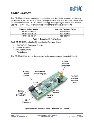
The RO2043 is a true one-port, surface-acoustic-wave (SAW) resonator in a low-profile TO39 case. It
provides reliable, fundamental-mode quartz frequency stabilization of fixed-frequency transmitters operating
at 303.825 MHz. The RO2043-1 is designed specitically for low-power AM transmitters on remote-control and
wireless alarm applications operating in the USA under FCC Part15, in Japan, in Australia, in Korea, and
elsewhere.
Absolute Maximum Ratings
Rating
Value
303.875 MHz
SAW
Resonator
Units
CW RF Power Dissipation
+5
dBm
DC Voltage Between Terminals (Observe ESD Precautions)
±30
VDC
-40 to +85
°C
Case Temperature
TO39-3 Case
Electrical Characteristics
Characteristic
Frequency (+25 °C)
Sym
Nominal Frequency
Tolerance from 303.875 MHz
Insertion Loss
fC
ΔfC
IL
QU
QL
Turnover Temperature
fO
Frequency Temperature Coefficient
Frequency Aging
2, 3, 4, 5
|fA|
DC Insulation Resistance between Any Two Pins
Typical
Units
MHz
±100
4.8
Maximum
303.975
303.775
kHz
7.0
dB
11300
5, 6, 7
4600
37
52
67
°C
fC+8.2
1, 6
5
kHz
0.037
6, 7, 8
FTC
Absolute Value during the First Year
Minimum
2, 5, 6
TO
Turnover Frequency
Temperature Stability
Unloaded Q
50 Ω Loaded Q
Quality Factor
Notes
ppm/°C2
ppm/yr
10
1.0
MΩ
Ω
Motional Resistance
RM
Motional Inductance
LM
Motional Capacitance
CM
Pin 1 to Pin 2 Static Capacitance
RF Equivalent RLC Model
CO
5, 6, 9
CP
5, 6, 7, 9
1.5
pF
LTEST
2, 7
150
nH
Transducer Static Capacitance
Test Fixture Shunt Inductance
74
5, 6, 7, 9
124
437.961
µH
.626346
1.5
Lid Symbolization (in addition to Lot and/or Date Codes)
1.8
fF
2.1
pF
RFM RO2043
CAUTION: Electrostatic Sensitive Device. Observe precautions for handling.
Notes:
1.
2.
3.
4.
5.
6.
7.
8.
9.
Frequency aging is the change in fC with time and is specified at +65°C or less. Aging may exceed the specification for prolonged temperatures
above +65°C. Typically, aging is greatest the first year after manufacture, decreasing significantly in subsequent years.
The center frequency, fC, is measured at the minimum insertion loss point, ILMIN, with the resonator in the 50 Ω test system (VSWR ≤ 1.2:1). The
shunt inductance, LTEST, is tuned for parallel resonance with CO at fC. Typically, fOSCILLATOR or fTRANSMITTER is less than the resonator fC.
One or more of the following United States patents apply: 4,454,488 and 4,616,197 and others pending.
Typically, equipment designs utilizing this device require emissions testing and government approval, which is the responsibility of the equipment
manufacturer.
Unless noted otherwise, case temperature TC = +25°C±2°C.
The design, manufacturing process, and specifications of this device are subject to change without notice.
Derived mathematically from one or more of the following directly measured parameters: fC, IL, 3 dB bandwidth, fC versus TC, and CO.
Turnover temperature, TO, is the temperature of maximum (or turnover) frequency, fO. The nominal frequency at any case temperature, TC, may be
calculated from: f = fO [1 - FTC (TO -TC)2]. Typically, oscillator TO is 20°C less than the specified resonator TO.
This equivalent RLC model approximates resonator performance near the resonant frequency and is provided for reference only. The capacitance
CO is the static (nonmotional) capacitance between pin1 and pin 2 measured at low frequency (10 MHz) with a capacitance meter. The measurement
includes case parasitic capacitance with a floating case. For usual grounded case applications (with ground connected to either pin 1 or pin 2 and to
the case), add approximately 0.25 pF to CO.
www.RFM.com
E-mail: info@rfm.com
©2008 by RF Monolithics, Inc.
Page 1 of 2
RO2043 - 3/25/08