عضویت
عضویت  ورود اعضا
 راهنمای خرید


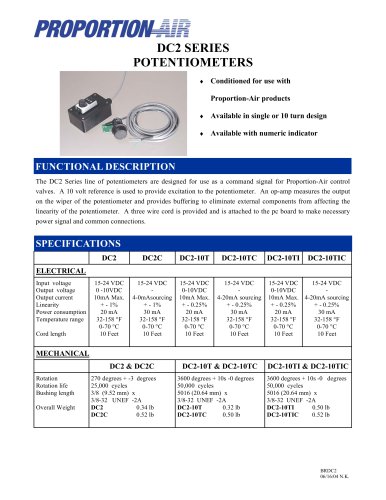
QB4 PRESSURE CONTROL VALVE0 pages
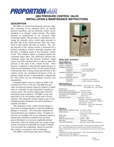
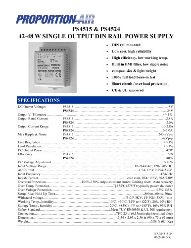
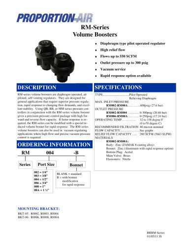
table.main {} tr.row {} td.cell {} div.block {} div.paragraph {} .font0 { font:11.00pt "Arial", sans-serif; } .font1 { font:12.00pt "Arial", sans-serif; } .font2 { font:14.00pt "Arial", sans-serif; } .font3 { font:17.00pt "Arial", sans-serif; } .font4 { font:24.00pt "Arial", sans-serif; } .font5 { font:50.00pt "Arial", sans-serif; } PROPORTION QB4 PRESSURE CONTROL VALVE INSTALLATION & MAINTENANCE INSTRUCTIONS DESCRIPTION The QB4 is a closed loop electronic pressure regu-lalor consisling of two solenoid valves, an internai pressure iransducer, and an electronic eonlrol circuit nk>unted to an inlegral volume booster. The ouipui pressure is proporlional to an electrical inpu (command signal). The pressure iscontrolled hy acti-vaiing the solenoid valves, which apply pressure to Ihe pilot side of the volume booster. One valve fonctions as inlet control, the other as exhaust. The out-put pressure of the volume booster is measured by a pressure transducer, which is intemally mounted, and provides a feedback signal to the electronic control circuit. This feedback signal is compared againsl the command signal inpuL Any diffﭩrences between the command signal and the pressure feedback signal causes onc of the solenod valves lo open to adjust the pressure in the pilot of the volume booster Pilot pressure is adjusted so that desired output pressure is achieved and mainlaincd. Sincc il is the aclual desired work pressure that is being sensed and fed back to the control circuit, any mechanical hystrsis of the air piloted volume booster is aulomatically compensated for. This allows for our extraordinary accuracy and rcpcatability. Command inputs corne in a choicc of either a dif-ferential 0-10 Vdc or 4-20 mA. The QB4 also provides an electrical monitor signal for output to a panel meter or conlroller for data acquisition orqualily asͭsurance needs. The monilor signal cornes from the internai pressure transducer. Ail QB4*s corne standard wilh a 0-10 volt monilor signal wilh 4-20 mA optional. Providing this monilor signal as part of our standard package ͩlimintes the need to purchasc a separate transducer The uniqueness of the volume booster design is lhat it has no stamped gaskets or spcial molded dia-phragm or seal paris. AU of the p;irts relaled lo nor⩭mal maintenance are standard o-rings. Complte repair kits are available, but in case emergency repair is needed parts should be available from any Iluid power distributor oreven mosl neighborhood hard譭ware stores. Since ail sealing parts are o-rings a large variety of chemical compounds are readily available. You can select the compounds, which are most ide-ally suited to your processandenvironment. The QB4 is used for pressures up to 150 psig. SPECIFICATIONS ELECTRICAL SUPPLY VOLTAGE........................15-24 VDC SUPPLY CURRENT..................250mA ma*. COMMAND SIGNAL VOLTAGE......................(MO VDC differenlial CURRENT.....................4-20mA difTcrcntia] COMMAND SIGNAL IMPEDANCE VOLTAGE.......................lOKft CURRENT......................100 O ANALOG MONITOR SIGNAL VOLTAGE.....................0-10 VDC © 10mA max CURRENT...................4-20mA Sinking orSourcing MKCHANICAL AVAILABLE PRESSURE RANGES1... 29.9io. Hg(vac)- 150psig (760mmHg(vac) -1034 BAR) FLOW RATE IORWAKD A EXHAUST.............(See Elow Charts) F1LTRATION RECOMMENDED. ..40 micron actual LINEARITY/HYSTERESE...........<±*\.y\ M H F SI. ■ ACCURACY..................................<±0,4* F S. * WETITiDPARTSt...............Elastomm- Ni!rile(3) Manifold - Aluniinum Nickel Plaled Sofenoid Valves - 430FR SS, 360 Brass Seal material - Nitrile PTransducer- Utem 1000. Aluminum, Silicon OPERATINC TEMPERATURE..J2-I58T |0-70°C| DIMENSIONS.........................3in. X 31a X 6.5in, (76.2mm X 76.2mm X 165.1 mitn PORT SEE............................1/2" NPTF WEIGHT........................................3.7lb[l.7KgI PROTECTION RAT1NG.............NEMA 4/ IP65 HOUSENG____.........mm...................Aluminum (Anodized) VOLUME BOOSTER....................Ebctrotess Nickel Plated Aluminum 1 Pressure ranges are cuslomcrspccified. Cualom pressure ranges are avajl-sbte. Vacuum througb positive pressure units* positive pressure must be equal to greater than vacuum teveL Consult factory for pressure range below 10 psig, * D٩pendent on response adjustments. Valve can be field adjusced foc besl response for the aclual application 1 Other elastomers are available. Consult factory. HQB4 \ui\m km 1/5
"