عضویت
عضویت  ورود اعضا
 راهنمای خرید


Steam Traps0 pages

tr.row {}
td.cell {}
div.block {}
div.paragraph {}
.font0 { font:7.00pt "Arial", sans-serif; }
.font1 { font:9.00pt "Arial", sans-serif; }
.font2 { font:10.00pt "Arial", sans-serif; }
.font3 { font:12.00pt "Arial", sans-serif; }
.font4 { font:12.60pt "Arial", sans-serif; }
.font5 { font:13.00pt "Arial", sans-serif; }
.font6 { font:21.00pt "Arial", sans-serif; }
PT10
Thermodynamic Steam Traps
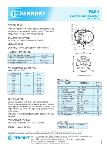
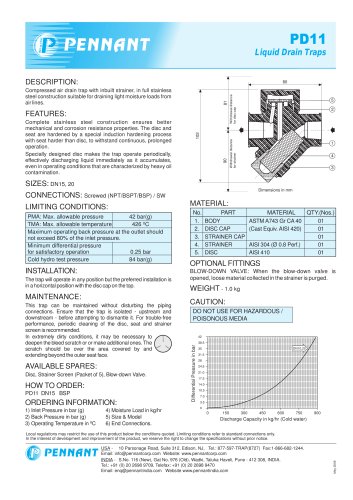
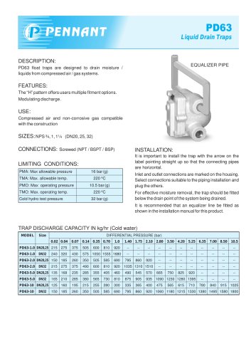
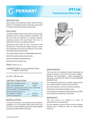
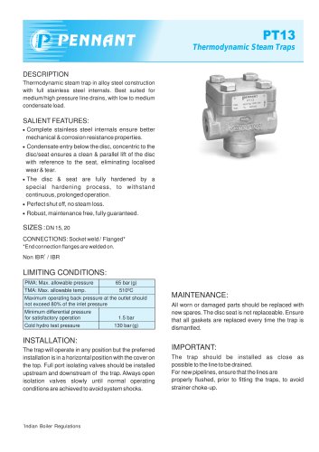
DESCRIPTION:
Thermodynamic steam trap with inbuilt strainer in full stainless steel construction, bestsuited for headerand main line drains and drip legs.
FEATURES:
Complete stainless steel construction ensures better mechanical and corrosion resistance properties. The disc and seat are hardened by a special induction hardening process with seat harder than disc, to withstand continuous, prolonged operation. Condensate entry below the disc, concentric to the disc / seat ensures a clean and parallel lift of the disc with reference to the seat, eliminating localized wear andtear.
The inbuiltstrainerscreen isof adequately large area. Ideal forfluctuating loads and pressures. Perfectshut-off, no steam loss.
SIZE:DN15
CONNECTIONS : Screwed (NPT/BSPT/BSP) Socket weld
Non IBR1 / IBR approved
MAINTENANCE:
This trap can be maintained without disturbing the piping connections. Ensure that the trap is isolated -upstream and downstream - before attempting to dismantle it. ALLOW THE TRAP TO COOL BEFORE DISMANTLING.
For trouble-free performance, periodic cleaning ofthe disc, seat and strainerscreen is recommended. Do not use abrasive/corrosive mediaforcleaning. Only the disc and seat are subject to wear. Aworn disccan be replaced. Slightseatwearcan often be corrected by resurfacing on a lap plate.
IMPORTANT:
The trap should be installed as close as possible to the system drain point. For new installations, the system should be properly flushed prior to fitting the trap.
LIMITING CONDITIONS:
PMA: Max. allowable pressure
21 bar (g)
TMA: Max. allowable temp.
426 °C
Maximum operating back pressure at the outlet should not exceed 80% of the inlet pressure.
Minimum differential pressure for satisfactory operation
0.25 bar (g)
Cold hydro test pressure
42 bar (g)
INSTALLATION:
The trap will operate in any position but the preferred installation is in the horizontal plane with the disc cap on the top. Full port isolating valves should be installed upstream and downstream of the trap.
Always open isolation valves slowly until normal operating conditions are achieved to avoid system shocks.
Indian Boiler Regulations