عضویت
عضویت  ورود اعضا
 راهنمای خرید


Electrical Tomography Software Res3dinv0 pages
- A L^riHiEiia
DATA INVERSION SOFTWARE FOR □Slfxl
ELECTRICAL IMAGING AND INDUCED
IZATION (IP) RES3DINV
This software has been developped for the inversion of data
collected as to an electrode grid with rectangular meshes
(Loke & Barker, 1996). The spreadings being supported
include Pole-Pole, Pole-Dipole, line Dipole-Dipole, equatorial
Dipole-Dipole and Wenner-Schlumberger.
RES3DINV uses the minimum squares method to produce
a sub-soil 3D model starting from the data of apparent
resistivity. We warmly recommend to use a computer with
minimum the following features: microprocessor Pentium
II or IH\ 64Mb of RAM and hard disk of 6.4 Gb.
Further to the dimensions of the grid and the number of
acquisitions, the 3D inversion of a single set of data may
as a matter of fact require from a few minutes up to more
that 12 hours, depending on the performance of your PC.
The program automatically selects the best inversion
parameters for a certain set of data (those parameters may
anyway be modified by the user). Three different versions
of the minimum squares method are available for the
inversion: a fast 'almost-Newton* method, a slower and
more accurate 'Gauss-Newton* method, and finally a hybrid
technique, rather fast and accurate at the same time.
The 'smoothing* filter may be adjusted in two different ways:
the first way is optimized for those areas that are characterized
by a gradual variation of the resistivity with the depth, the
other way is optimized for areas with very clear-cut variations.
The topographical corrections may be entered using a
'distorted* grid of finished elements in order to coincide with
the topographical undulations (Sazaki 1994)
0.0
10
3D
Lernacken Sludge Dep
00 1 0 20 30 40 SO SO 70 80 90100 0.0
o.o
□ sit survey
10 20 30 40 SO BO 70 SO 90100
Layer 1 Depln: 0.00-3.50 m.
0.0 10 20 30 40 50 SO 70 SO
0.0
Layer 2 Depth : 3.50-7.53 m.
10 20 30 40 SO BO 70 SO 90100
Layer 3 Oeplh : t 53 12.2 m.
0.0 10 20 3D 4D 50 60 70 80 90100
DO
Layer 4 Depth 12.2-17.S m.
10 20 30 40 SO 00 70 80 90100
Layers Depot 117 5-23.6 m
X Unit Electrode Spacing S.OM, V Unit Bei
116 tall on G - RMS Error B.T<H>
Layer B Depth ; 23 8-30 6 m.
e Spacing 5.0M.
2.0 4.0 0.0 16.0 32.0 64.0
Resistivity In Oh mm
Time tsken(200 MHz Pentium Prol t5162»eis.
120
256
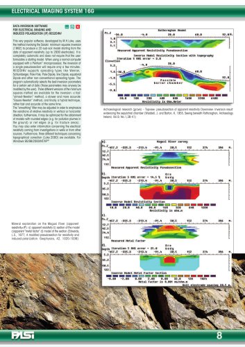
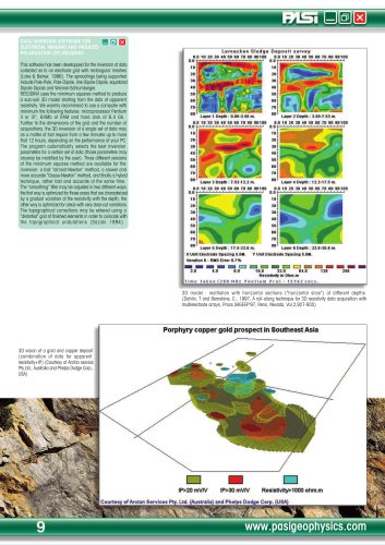
3D model : restitution with horizontal sections ('horizontal slice*) at different depths
(Dahlin, T and Bernstone, C, 1997, A roll-along technique for 3D resistivity data acquisition with
multielectrode arrays, Procs.SAGEEP'97, Reno, Nevada, Vol.2,927-935)
3D vision of a gold and copper deposit
(combination of data for apparent
resistivity+IP) (Courtesy of Arctan service
Pfy.Ltd., Australia and Phelps Dodge Corp.,
USA)
Porphyry copper gold prospect in Southeast Asia
IP>20mV/V IP>30mV/V Resist! vity>1000 ohm.m
I Courtesy of Arctan Services Pty. Ltd. (Australia) and Phelps Dodge Corp. (USA)
www.pasigeophysics.com
"