عضویت
عضویت  ورود اعضا
 راهنمای خرید


Model M1433B 6 RTD ISO0 pages
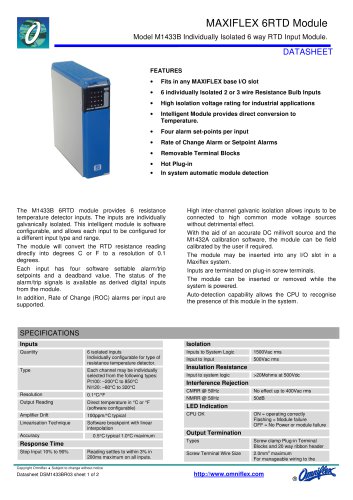
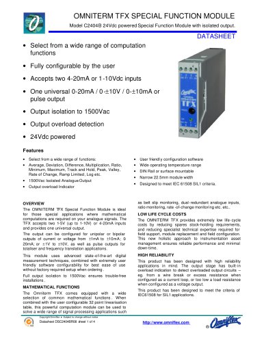
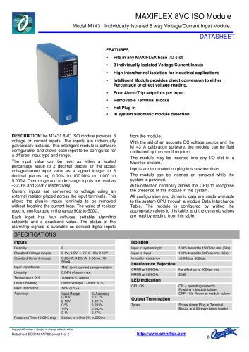
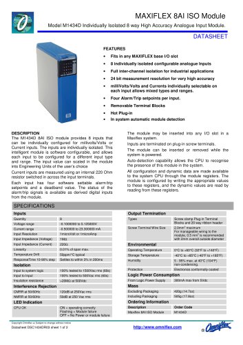
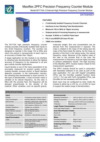
MAXIFLEX 6RTD Module
Model M1433B Individually Isolated 6 way RTD Input Module.
DATASHEET
FEATURES
•
Fits in any MAXIFLEX base I/O slot
•
6 individually Isolated 2 or 3 wire Resistance Bulb Inputs
•
High isolation voltage rating for industrial applications
•
Intelligent Module provides direct conversion to
Temperature.
•
Four alarm set-points per input
•
Rate of Change Alarm or Setpoint Alarms
•
Removable Terminal Blocks
•
Hot Plug-in
•
In system automatic module detection
The M1433B 6RTD module provides 6 resistance
temperature detector inputs. The inputs are individually
galvanically isolated. This intelligent module is software
configurable, and allows each input to be configured for
a different input type and range.
The module will convert the RTD resistance reading
directly into degrees C or F to a resolution of 0.1
degrees.
Each input has four software settable alarm/trip
setpoints and a deadband value. The status of the
alarm/trip signals is available as derived digital inputs
from the module.
In addition, Rate of Change (ROC) alarms per input are
supported.
High inter-channel galvanic isolation allows inputs to be
connected to high common mode voltage sources
without detrimental effect.
With the aid of an accurate DC millivolt source and the
M1432A calibration software, the module can be field
calibrated by the user if required.
The module may be inserted into any I/O slot in a
Maxiflex system.
Inputs are terminated on plug-in screw terminals.
The module can be inserted or removed while the
system is powered.
Auto-detection capability allows the CPU to recognise
the presence of this module in the system.
SPECIFICATIONS
Inputs
Quantity
Type
Isolation
6 isolated inputs
Individually configurable for type of
resistance temperature detector.
Each channel may be individually
selected from the following types:
Pt100: –200°C to 850°C
Ni120: –80°C to 320°C
Resolution
0.1°C/°F
Output Reading
Direct temperature in °C or °F
(software configurable)
Amplifier Drift
100ppm/°C typical
Linearisation Technique
Software breakpoint with linear
interpolation
Accuracy
0.5°C typical 1.0°C maximum
1500Vac rms
Input to Input
500Vac rms
Insulation Resistance
Input to system logic
>20Mohms at 500Vdc
Interference Rejection
CMRR @ 50Hz
No effect up to 400Vac rms
NMRR @ 50Hz
50dB
LED Indication
CPU OK
ON = operating correctly
Flashing = Module failure
OFF = No Power or module failure
Output Termination
Types
Response Time
Step Input 10% to 90%
Inputs to System Logic
Reading settles to within 3% in
200ms maximum on all inputs.
Screw clamp Plug-in Terminal
Blocks and 20 way ribbon header
Screw Terminal Wire Size
2.0mm2 maximum
For manageable wiring to the
Copyright Omniflex ♦ Subject to change without notice
Datasheet DSM1433BR03 sheet 1 of 2
http://www.omniflex.com
®
"