عضویت
عضویت  ورود اعضا
 راهنمای خرید


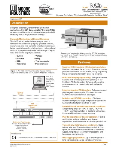
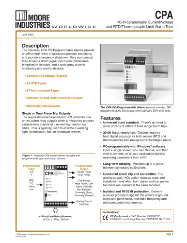
Signal Transmitters, Isolators and Converters0 pages
Signal Isolators, Converters and Interfaces:
nnThe InsӔ and OutsӔ nnNovember 2008 By using the right signal interface instruments, in the right ways, potential problems can be easily avoided well before they boil over... quite literally in some cases. Whether you call them signal isolators, signal converters or signal interfaces, these useful process instruments solve important ground loop and signal conversion chal-
lenges everyday. Just as important, they are called upon to do a whole lot more. They can be used to share, split, boost, protect, step down, linearize and even digitize pro-
cess signals. This guide will tell you many of the impor-
tant ways signal isolators, converters and interfaces can be used, and what to look for when specifying one. >
In addition to simple signal isolation and conversion, signal interface instruments can be used to share, split, boost, protect, step down, linearize and even digitize process signals.
The need for signal isolation began to fl ourish in the 1960s and continues today. Electronic transmitters were quickly replacing their pneumatic predecessors because of cost, installation, maintenance and performance advantages. However, it was soon discovered that when 4-20mA (or other DC) signal wires have paths to ground at both ends of the loop, problems are likely to occur. The loop in question may be as simple as a differential pressure (DP) transmitter sending a 4-20mA measure-
ment to a receiver, such as a recorder. But when the voltages (V) at the two ground points are different, a circulating, closed current (I) path is formed by the copper wires used for the 4-20mA signal and the ground (Figure 1). When this happens, an additional and unpredictable amount of current is introduced into the loop, which distorts the true measurement. This current path, known as a ground loop, is a very common source of signal inaccuracies.A ground loop forms when three conditions are present: To remove the ground loop, any one of these three conditions must be eliminated. The challenge is, the fi rst and second conditions are not plausible candidates for elimination. Why? Because you cannot always control the number of grounds, and it is often impossible to just liftӔ a ground. The ground may be required for the safe operation of an electronic device. Its also possible that the ground exists because the instrument is in physical contact with the process which, in turn, is in physical contact with the ground. From a practical standpoint, you cannot reach into the earth and regulate the voltage at these perma-
nent ground points. >
Figure 2. A signal isolator ғbreaks the galvanic path between two grounds. ISOLATOR +24V+Ԗ++֖ NON-ISOLATED TRANSMITTER4-20mA ISOLATED4-20mABREAKS THEGALVANIC PATH RECEIVER RECEIVER optoisolation +IN 1. There are two grounds; >
+24V 2. The grounds are at different potentials; >
V1 V2 3. There is a galvanic path between the grounds. >
POWER SUPPLY Figure 1. A ground loop forms when the voltages at two ground points in a loop are at different potentials. +24V+֖ So what can be done? Use a signal isolator to breakӔ the galvanic path between the two grounds (Figure 2). When the conductive path between the differential voltages is broken, a current cannot form. So even though there are two grounds and different voltages at each ground, there is no current fl ow. The ground loop has been eliminated. >
NON-ISOLATED TRANSMITTER 4-20mAV2 RECEIVER RECEIVER +IN GROUND LOOP IӔ V1 The Interface Solution Experts www.miinet.com >
թ2008 Moore Industries-International, Inc. Page 1 size="-1">