عضویت
عضویت  ورود اعضا
 راهنمای خرید


Model TW-STEP General Use Thermowells0 pages
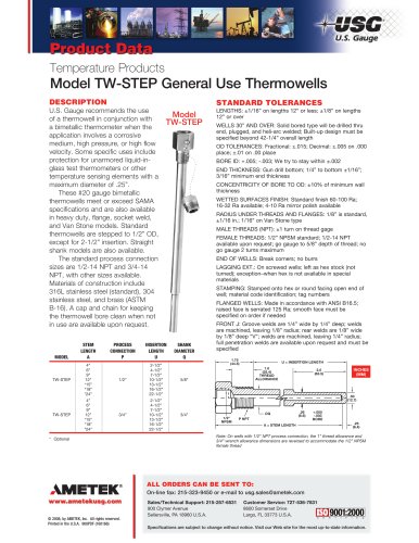
Temperature Products
Model TW-STEP General Use Thermowells
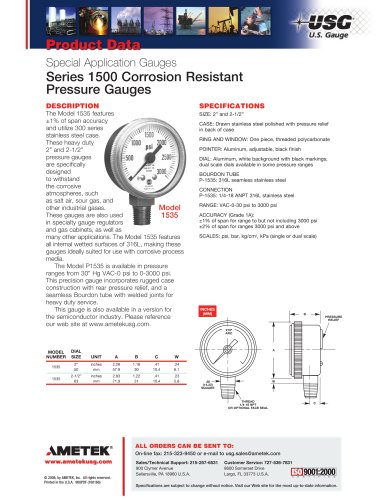
DESCRIPTION
U.S. Gauge recommends the use
of a thermowell in conjunction with
a bimetallic thermometer when the
application involves a corrosive
medium, high pressure, or high flow
velocity. Some specific uses include
protection for unarmored liquid-inglass test thermometers or other
temperature sensing elements with a
maximum diameter of .25”.
t These #20 gauge bimetallic
thermowells meet or exceed SAMA
specifications and are also available
in heavy duty, flange, socket weld,
and Van Stone models. Standard
thermowells are stepped to 1/2” OD,
except for 2-1/2” insertion. Straight
shank models are also available.
t The standard process connection
sizes are 1/2-14 NPT and 3/4-14
NPT, with other sizes available.
Materials of construction include
316L stainless steel (standard), 304
stainless steel, and brass (ASTM
B-16). A cap and chain for keeping
the thermowell bore clean when not
in use are available upon request.
t MODELt
STEMt
LENGTHt
At
PROCESSt
CONNECTIONt
Pt
STANDARD TOLERANCES
Model
TW-STEP
INSERTIONt
LENGTHt
Ut
WELLS 30” AND OVER: Solid bored type will be drilled thru
end, plugged, and heli-arc welded; Built-up design must be
specified beyond 42-1/4” overall length
OD TOLERANCES: Fractional: ±.015; Decimal: ±.005 on .000
place; ±.01 on .00 place
BORE ID: +.005; -.003; We try to stay within ±.002
END THICKNESS: Gun drill bottom; 1/4” to bottom ±1/16”;
3/16” minimum end thickness
CONCENTRICITY OF BORE TO OD: ±10% of minimum wall
thickness
WETTED SURFACES FINISH: Standard finish 60-100 Ra;
16-32 Ra available; 4-10 Ra mirror polish available
RADIUS UNDER THREADS AND FLANGES: 1/8” is standard,
±1/16 in.; 1/16” on Van Stone type
MALE THREADS (NPT): ±1 turn on thread gage
FEMALE THREADS: 1/2” NPSM standard; 1/2-14 NPT
available upon request; go gauge to 5/8” depth of thread; no
go gauge 2 turns maximum
END OF WELLS: Break corners; no burrs
LAGGING EXT.: On screwed wells; left as hex stock (not
turned); exception–when hex is not available in special
materials
STAMPING: Stamped onto hex or round facing open end of
well; material code identification; tag numbers
FLANGED WELLS: Made in accordance with ANSI B16.5;
raised face is serrated 125 Ra; smooth face must be
specified on order if needed
SHANKt
DIAMETERt
Q
t TW-STEPt
4” tt
6”tt
9” tt
12” t
1/2” t
*15” tt
*18” tt
*24” tt
2-1/2”tt
4-1/2”tt
7-1/2”tt
10-1/2” t
5/8”t
13-1/2”tt
16-1/2”tt
22-1/2”
t TW-STEPt
4” tt
6” tt
9” tt
12”t
3/4” t
*15” tt
*18” tt
*24” tt
2-1/2”tt
4-1/2”tt
7-1/2”tt
10-1/2”t
3/4”t
13-1/2”tt
16-1/2”tt
22-1/2”
*t Optional
LENGTHS: ±1/16” on lengths 12” or less; ±1/8” on lengths
12” or over
FRONT J: Groove welds are 1/4” wide by 1/4” deep; welds
are machined, leaving 1/8” radius; rear welds are 1/8” wide
by 1/8” deep “V”; welds are machined, leaving 1/4” radius;
full penetration welds are available upon request and must be
specified
1.75
(44.5)
U = INSERTION LENGTH
1.0
(25.4)
THREAD
ALLOWANCE
2.5
(63.5)
INCHES
(MM)
.50
(12.7)
1/2"
NPSM
øQ
P NPT
.26
(6.6)
+.005
-.003
BORE
A = STEM LENGTH
.25
(6.4)
Note: On wells with 1/2” NPT process connection, the 1” thread allowance and
3/4” wrench allowance dimensions are reversed to accommodate the 1/2” NPSM
female thread
ALL ORDERS CAN BE SENT TO:
On-line fax: 215-323-9450 or e-mail to usg.sales@ametek.com
© 2008, by AMETEK, Inc. All rights reserved.
Printed in the U.S.A. 908PDF (160166)
Sales/Technical Support: 215-257-6531t
900 Clymer Avenuet
Sellersville, PA 18960 U.S.A.t
Customer Service: 727-536-7831t
8600 Somerset Drive
Largo, FL 33773 U.S.A.
Specifications are subject to change without notice. Visit our Web site for the most up-to-date information.