عضویت
عضویت  ورود اعضا
 راهنمای خرید


Pressure Reducing Valves DM 6620 pages
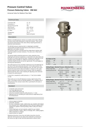
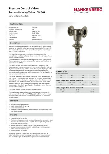
Pressure Control Valves
Pressure Reducing Valves DM 662
Page No. DM 662/2.1.128.1 - Standing 18.09.2012
MANKENBERG GmbH | Spenglerstraße 99 | D-23556 Lübeck
www.mankenberg.de | Tel. +49 (0) 451 - 8 79 75 0
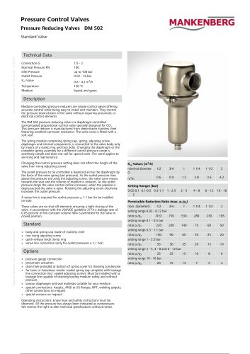
Universal Valve for Medium Flow Rate
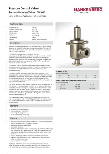
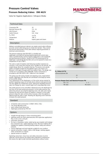
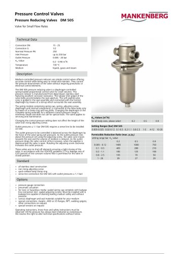
Technical Data
Connection DN
Connection G
Nominal Pressure PN
Inlet Pressure
Outlet Pressure
Kvs-Value
Temperature
Medium
15 - 25
1/2 - 1
100
up to 100 bar
0.02 - 12 bar
3.2 - 3.6 m3/h
130 °C
liquids and gases
Description
Medium-controlled pressure reducers are simple control valves offering
accurate control while being easy to install and maintain. They control
the pressure downstream of the valve without requiring pneumatic or
electrical control elements.
The DM 662 pressure reducing valve is a diaphragm-controlled
spring-loaded and balanced proportional control valve for universal
application and medium volumes.
This pressure reducer is manufactured from deep-drawn stainless steel
featuring excellent corrosion resistance. The valve cone is fitted with a
soft seal.
The spring module comprising spring cap, spring, adjusting screw,
diaphragm and internal components, is connected to the valve body only
by means of a clamp ring and two bolts. Changing the diaphragm or the
complete spring assembly for a different control pressure range is
extremely simple and does not call for special tools. The same applies to
servicing and maintenance.
The outlet pressure to be controlled is balanced across the diaphragm by
the force of the valve spring (set pressure). As the outlet pressure rises
above the pressure set using the adjusting screw, the valve cone moves
towards the seat and the volume of medium is reduced. As the outlet
pressure drops the valve control orifice increases; when the pipeline is
depressurised the valve is open. Rotating the adjusting screw clockwise
increases the outlet pressure.
A sense line is required for outlet pressures ≤ 1.1 bar (to be installed
on-site).
These valves are no shut-off elements ensuring a tight closing of the
valve. In accordance with the VDI/VDE guideline 2174 a leakage rate of
0.05 percent of the constant volume flow is permitted for the valve in
closed position.
Standard
»
»
»
»
»
all stainless steel construction
non rising adjusting screw
quick-release body clamp ring
sense line connection (only for outlet pressures ≤ 1.1 bar)
balanced cone for controlling the outlet pressure indipendently from
the initial pressure
Options
» pressure gauge connection
» pneumatic actuation
» for toxic or hazardous media: sealed spring cap complete with leakage
line connection (incl. sealed adjusting screw). Must be installed with a
leakage line capable of draining leaking medium safely and without
pressure
» various diaphragm and seal materials suitable for your medium
» special connections: Aseptic, ANSI or JIS flanges, NPT, welding spigots;
other connections on request
» special versions on request
Operating instructions, know how and safety instructions must be
observed. All the pressure has always been indicated as overpressure.
We reserve the right to alter technical specifications without notice.
Kvs-Values [m3/h]
nominal
DN
diameter
G
Kvs-value
m3/h
15
1/2
3.2
20
3/4
3.5
Setting Ranges, Nominal Pressure, Reduction Ratio
setting range [bar]
6 - 12
4-8
2-5
nominal pressure PN
BSP female connection
100/16
100/16
100/10
flange connection
40/16
40/16
40/10
p1/p2 max.
15
15
20
Setting Ranges, Nominal Pressure, Reduction Ratio
setting range [bar]
0.3 - 1.1
0.1 - 0.5
nominal pressure PN
BSP female connection
100/2.5
100/1
flange connection
40/2.5
40/1
p1/p2 max.
60
150
25
1
3.6
0.8 - 2.5
100/6
40/6
45
0.02 - 0.12
100/1
40/1
510