عضویت
عضویت  ورود اعضا
 راهنمای خرید


SP2500-H/C/I/BB0 pages
Embracing Challenge
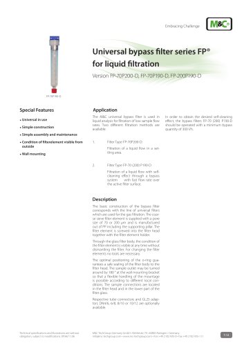
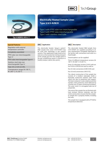
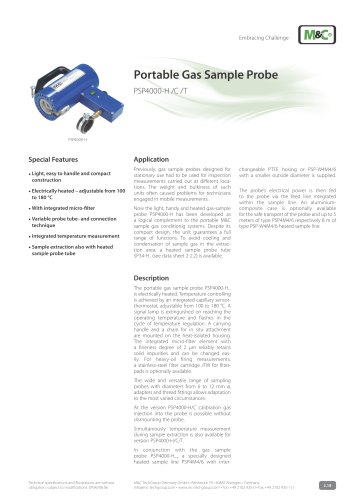
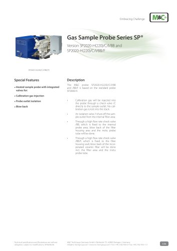
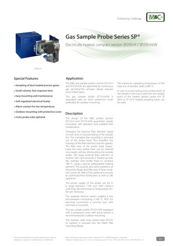
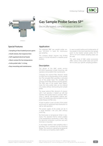
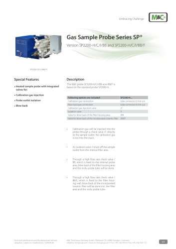
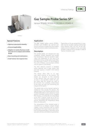
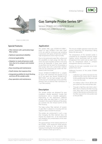
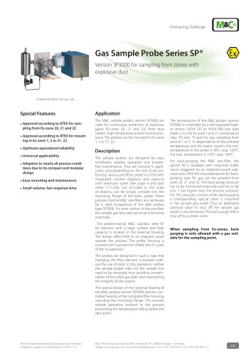
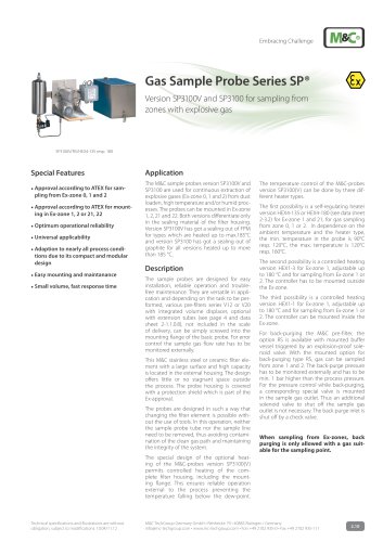
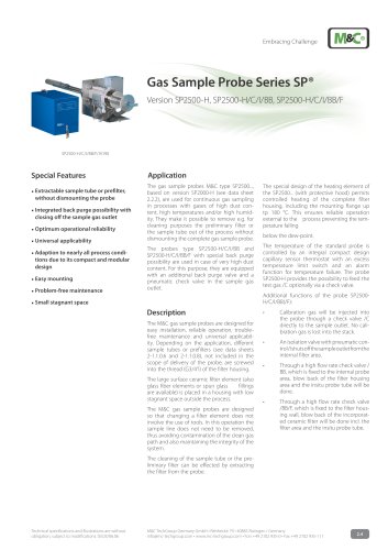
Gas Sample Probe Series SP®
Version SP2500-H, SP2500-H/C/I/BB, SP2500-H/C/I/BB/F
SP2500-H/C/I/BB/F/1K190
Special Features
Extractable sample tube or prefilter,
without dismounting the probe
I
ntegrated back purge possibility with
closing off the sample gas outlet
Optimum operational reliability
Universal applicability
Adaption to nearly all process condi-
tions due to its compact and modular
design
Easy mounting
Problem-free maintenance
Application
The gas sample probes M&C type SP2500...,
based on version SP2000-H (see data sheet
2.2.2), are used for continuous as sampling
g
in processes with gases of high dust content, high temperatures and/or high humidity. They make it possible to remove e.g. for
cleaning purposes the preliminary filter or
the sample tube out of the process without
dismounting the complete gas sample probe.
The special design of the heating element of
the SP2500... (with protective hood) ermits
p
controlled heating of the complete filter
housing, including the mounting flange up
tp 180 °C. This ensures reliable operation
e
xternal to the process preventing the temperature alling
f
The probes type SP2500-H/C/I/BB and
SP2500-H/C/I/BB/F with special back purge
possibility are used in case of very high dust
content. For this purpose, they are equipped
with an additional back purge valve and a
pneumatic check valve in the sample gas
outlet.
The temperature of the standard probe is
controlled by an integral compact design
capillary sensor hermostat with an excess
t
temperature limit switch and an alarm
function for emperature failure. The probe
t
SP2500-H provides the possibility to feed the
test gas /C optionally via a check valve.
below the dew-point.
Additional functions of the probe SP2500H/C/I/BB(/F):
Small stagnant space
Description
The M&C gas sample probes are designed for
easy installation, reliable operation, troublefree maintenance and universal applicability. Depending on the application, different
sample tubes or prefilters (see data sheets
2-1.1.0.6 and 2-1.1.0.8), not included in the
scope of delivery of the probe, are screwed
into the thread (G3/4”i) of the filter housing.
The large surface ceramic filter element (also
glass fiber elements or spun glass
fillings
are available) is placed in a housing with low
stagnant space outside the process.
The M&C gas sample probes are designed
so that changing a filter element does not
involve the use of tools. In this operation the
sample line does not need to be removed,
thus avoiding contamination of the clean gas
path and also maintaining the ntegrity of the
i
system.
• t
Calibration gas will be injected into
the probe through a check valve /C
directly to the sample outlet. No calibration gas is lost into the stack.
•t
An isolation valve with pneumatic control /I shuts off the sample outlet from the
internal filter area.
• t
Through a high flow rate check valve /
BB, which is fixed to the internal probe
area, blow back of the filter housing
area and the insitu probe tube will be
done.
• t
Through a high flow rate check valve
/BB/F, which is fixed to the filter housing wall, blow back of the incorporated ceramic filter will be done incl. the
filter area and the insitu probe tube.
The cleaning of the sample tube or the preliminary filter can be effected by extracting
the filter from the probe.
Technical specifications and illustrations are without
obligation, subject to modifications. 03.03/06.06
M&C TechGroup Germany GmbH • Rehhecke 79 • 40885 Ratingen • Germany
info@mc-techgroup.com • www.mc-techgroup.com • Fon +49 2102 935-0 • Fax +49 2102 935-111
2.4
"