عضویت
عضویت  ورود اعضا
 راهنمای خرید


PiezoStar® Accelerometer ? General Purpose, Voltage Mode Accelerometers0 pages

Acceleration
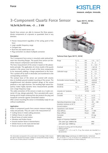
K-Beam® Accelerometer
Type 8395A...
Capacitive MEMS, Triaxial Accelerometer
Type 8395A… is a high-sensitivity, low-noise triaxial accelerometer which simultaneously measures acceleration and/or
low-frequency vibration in three mutually perpendicular axes
(x, y, z). The accelerometer features include:
•t Measuring ranges: ±2 g, ±10 g, ±30 g, ±50 g, ±100 g, ±200 g
•t Frequency response: 0 ... 1 000 Hz (5 %) (except ±2 g)
•t Bipolar ±4 V, single-ended 2,5 V ±2 V and ±4 V or ±8 V
differential accelerometer outputs
•t Operating temperature: –55 … 125 °C
•t Low-noise
•t Excellent thermal stability
•t Small cube, 30 grams mass
•t Wide supply voltage range, 5 … 50 VDC
•t 6 000 gpk shock rated
•t Conforming to ä
B
A
8395A_000-860e-05.13
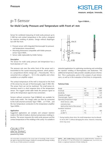
Description
Type 8395A… triaxial capacitive accelerometer family utilizes
a silicon Micro-Electro-Mechanical System (MEMS) variable
capacitance sensing element. The sensing element of each axis
consists of a very small inertial mass and a flexure element
cantilever positioned between two plates. As the mass deflects
under acceleration, the capacitance between these plates
changes. AC excitation and synchronous amplitude demodulation circuitry contained in the accelerometer's internal signal
conditioner provides an analog output signal proportional
to the applied acceleration. This output signal is scaled as a
voltage which is proportional to the applied acceleration.
The output signal format is available as bipolar 0 ±4 V, singleended 2,5 V ±2 V and 0 ±4 V or 0 ±8 V differential. The accelerometer is powered by a single regulated supply between 6
and 50 VDC (+5 VDC supply options are available as well on
request). Temperature output is provided if external compensation of the output signal is desired. The sensing element and
electronics are contained in a lightweight, welded titanium
housing with either a circular 9-pin connector or an integral
cable with braid shield protection terminated by pigtails or
9-pin D-Sub connector. Ground isolation is obtained by
mounting the sensor using one of the off-ground accessories
or by adhesively mounting the sensor to the test object using
the side of the sensor with the integral hard anodized plate.
C
Hard anodized plate
D
KIAG 10-32-2B thread
Outline Dimensions
A
B
C
D
AT, BT Versions
21,6
31
22,1
21,6
CT, DT Versions
21,6
34,5
22,1
21,6
Page 1/4
This information corresponds to the current state of knowledge. Kistler reserves
the right to make technical changes. Liability for consequential damage resulting
from the use of Kistler products is excluded.
©2007 ... 2013, Kistler Group, Eulachstrasse 22, 8408 Winterthur, Switzerland
Tel. +41 52 224 11 11, Fax +41 52 224 14 14, info@kistler.com, www.kistler.com
Kistler is a registered trademark of Kistler Holding AG.